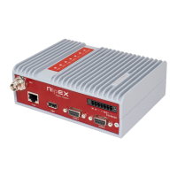
9. Dummy load antenna
Fig. 4.30: Dummy load antenna
Dummy load antenna for RipEX is
used to test the configuration on a
desk. It is unsuitable for higher
output – use transmitting output of
1.0 W only.
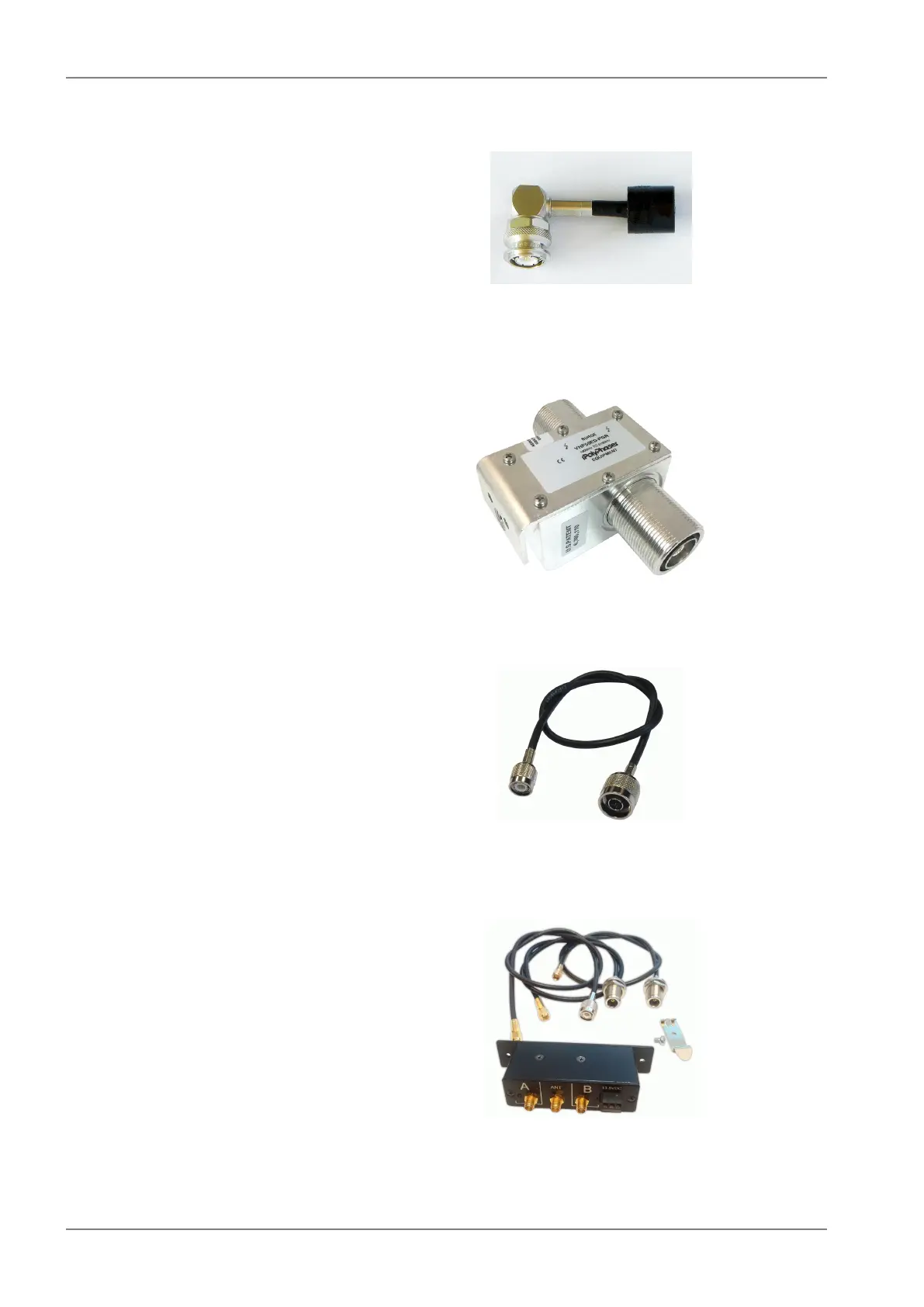
10. Coaxial overvoltage protection
Fig. 4.31: Overvoltage protection
Frequency range 100-512 MHz,
connectors N(female) / N(female).
11. Feedline adapter cable
Fig. 4.32: Feedline adapter cable
Feedline cable is 50 cm long and
is made from the RG58 coaxial
cable. There are TNC Male (RipEX
side) and N Male connectors on
the ends. It is intended for use
between RipEX and cabinet panel.
12. Automatic antenna switch
Fig. 4.33: Automatic antenna switch
An Automatic antenna switch is
mainly used for migrating legacy
to RipEX networks. It automatically
manages antenna switching: when
one base station transmits, the
other one is disconnected from the
common antenna.
RipEX Radio modem & Router – © RACOM s.r.o.78
Product