D9000/D7000 Series Operation & Installation Manual
Page 19
74-07692-000-C 4/97
The Radionics defaults set relay A (terminal 6)
as a Steady Alarm Bell output and relay A
(terminal 7) as a Pulsed Fire Bell output, and
relay C (terminal 8) as a Verification/Reset
output for smoke detectors. The
D9000/D7000
Series Program Entry Guide
(74-07695-000)
contains complete instructions for programming
relays. Descriptions of the functional
characteristics of each terminal appear on the
next page.
See the
Bell Parameters
section of the program
to set the Fire Bell, Alarm Bell output responses
for relays. Four annunciation patterns: Steady,
Pulsed, California Standard, and Temporal Code
3 are available.
Unexpected Output at Terminals 6, 7 and 8:
If
terminals 6, 7, and 8 don’t provide the output you
expect:
• Check the programming for relays A, B, and
C in the
Relays
module of the program.
• Check the
Bell Parameters
section of the
program to verify the Alarm and Fire Bell
responses are programmed for the duration
and pattern you expect.
• Check the
Point Assignments
to verify each
point is programmed for the local response
you expect.
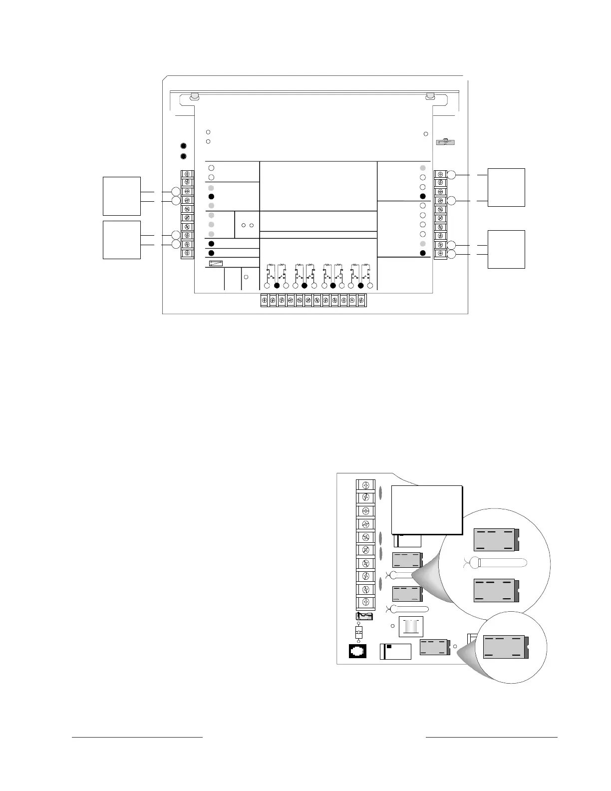
Figure 5: Connecting D8132 Modules
5
9
10
1
2
Low Battery
LEDs Off Wh en Normal
EARTH GROUND
COMMON
CLAS S 2 TRANSFORMER
16.5 VAC 40 VA 60 HZ
Part No. D1640
Internally Fused - Do Not Short
Requires Unswitched Outlet
Do Not Share With Other Equipment
+ AUX POWER
BATTERY NEGATIVE O NLY
Maximum Charging
Current 1.4 Amps.
PHONE MONITOR SELECT
Loop Start
Ground Start
TELCO
COR D
PHONE
LED
ON WHEN
COMMUNICATING
OFF WHEN IDLE
Re q u ire s
Relay
#D136
ON-BOARD POINTS
1.0K Resistor
Required at End of Line
Ω
VOLTAGE RANGES
Open 3.7 - 5.0VDC
Norm al 2.0 - 3.0VDC
Short 0.0 - 1.3VDC
PERIPHERAL DEVICE WIRING
ZONEX OUT 1
ZONEX IN 1
ZONEX OUT 2
ZONEX IN 2
ZONEX POWER +
ZONEX COMM ON
Operation Monitor
Pulses When Normal
Flickers When Ringing
PROG
CONN
RED
YELLOW
GREEN
BLACK
17-05823-002
32
POWER +
DATA B U S A
COMMON
RE D
GROUND
START
YE L
RED
Reset Pin
Disable All Except Battery
Charging And Programming
GR N
STEADY O R
PULSE
+
Ch ar ging S tat us
N.F.P.A.
Style 3.5
Signaling
Line
Ci r cu its
12
15 18 2113
11
14 16 17 19 20 22
PROGR AMMABLE
AL ARM OU T PU TS
Terminals
&
Req ui re
Opti onal
D136 Relay
in J1 & J9
7
Point 1 Point 2 Point 3 Point 4 Point 5 Point 6 Point 7 Point 8
DATA BUS B
29
31
30
24
23
28
27
26
25
BATTERY POSITIVE ONLY
+ ALTERNATE
SW ITC HE D
AUX POWER
+
6
7
8
8
3
4
+
-
3
4
8
9
+
-
32
29
D8132
1.4 Amps
+
-
24
23
D8132
1.4 Amps
+
-
D8132
1.4 Amps
D8132
1.4 Amps
1.4 Amps
NOTE
: Combined Total Dispersed
Current of 7.0 amps @ 12 VDC
M
Aromat
DS2E-M- DC12V
M Arom at
DS2E-M-DC12V
M
Arom at
DS2E-M-DC12V
J
K3/
J1
K1/
J9
GND START
K6/
J5
TOP
L
E
F
T
BOTTOM
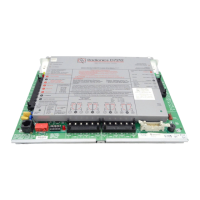
NOTE: The D136
relays are inserted
with the three pins
on the top side.
Figure 6: Relays for Terminals 7 and 8
and Ground Start
Optional Relays Required
Install an optional D136 plug-in relay into socket
J1 to enable the output at terminal 7. Install a
D136 in socket J9 to enable the output at terminal
8. The relay sockets are under the faceplate as
shown in Figure 6.
www.PDF-Zoo.com