D9000/D7000 Series Operation & Installation Manual
Page 35
74-07692-000-C 4/97
D811 Arm Status Relay Module
The D811 Arm Status Relay Module allows you
to add a single off-board relay output to your
system. You can assign alarm output, auxiliary
relay, sensor reset, arming status, point status,
alarm memory, or remote functions to the D811
relay output. You are not restricted to the arming
status mode only.
Relay numbers for D811 not programmable:
If
you connect the D811 to ZONEX 1, terminal 28 ,
you must use relay number 53 for the relay
output. If you connect the D811 to ZONEX 2,
terminal 26 on the D9412/D9112, you must use
relay number 117 for the relay output.
D811 modules connect as shown in Figure 18.
Review the
Power Outputs
section of this manual
to be sure you provide enough power for the
powered devices you wish to connect to your
system. See
Relay Parameters
in the
D9000/
D7000 Series Program Entry Guide
(74-07695-
000)
for programming details.
1234567 8
GND
D8125
POPEX
(-)
(-)
(+)
(+)
GND
OUT
IN
AUX
ZONEX OUT 1
ZONEX IN 1
ZONEX OUT 2
ZONEX IN 2
ZONEX COMMON
28
27
26
25
24
23
(-)
(-)
(+)
(+)
AUX
DA TA
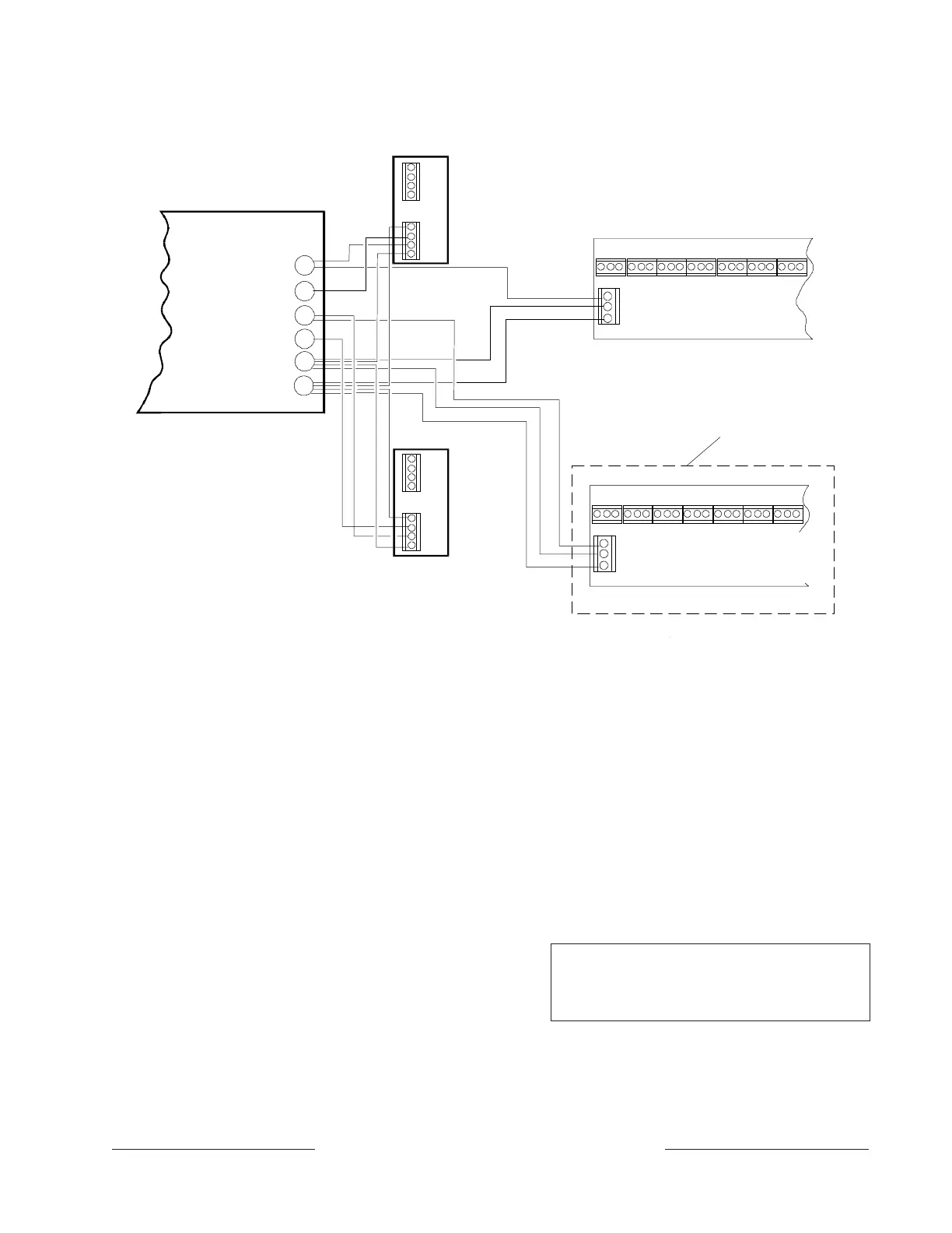
D8129 OCTORELAYS FOR RELAY
NUMBERS 65 TO 128. CONNECT
OCTORELAYS IN PARALLEL.
1234567 8
GND
AUX
DATA
D8129 OCTORELAYS FOR RELAY
NUMBERS 1 TO 64. CONNECT
OCTORELAYS IN PARALLEL.
ZONEX POWER +
GND
OUT
IN
AUX
D8125
POPEX
Control/Communicator
Panel
D9412/D9112 Only
Figure 15: D8129 OctoRelay Connections
D811 restricted for fire systems:
The D811
relay output is not supervised and can not be
used in fire or combined fire/burglary installations
for primary indication devices.
Relay Output
Each D811 relay output provides a Form C dry
contact rated for 1.0A at 12 VDC. Normally-open,
common, and normally-closed terminals are
available. When an individual output is activated,
there is continuity between the normally-open
and common terminals. When the output is not
activated, there is continuity between the
normally-closed and common terminals.
Warning:
Relay outputs may activate while
programming the panel. You may wish to
disconnect equipment connected to relay outputs
while performing these functions.
www.PDF-Zoo.com