D9000/D7000 Series Operation & Installation Manual
Page 23
74-07692-000-C 4/97
Set the ring count above 2 on answering
machines:
The line's RAM Monitor feature may
not operate correctly if you connect an answering
machine with a ring count of less than 2 rings, to
a phone line used by the D928 module.
Operation
The panel always uses the primary phone line to
initiate phone calls, unless it has been detected
as faulted. See
Phone Line Monitor
in this
manual for a description of the panel’s phone line
monitor operation.
See the
Phone
section of the
Panel Wide
Parameters
module of the
D9000/D7000 Series
Program Entry Guide
(74-07695-000) for phone
supervision and reporting options. You must set
the
Two Phone Lines
prompt to YES to use the
D928.
With the D928 Dual Phone Line Switcher
installed, the panel uses two phone lines, primary
and secondary, to dial up to four phone numbers.
When using only a Primary Device within a Route
Group #, the panel will make two attempts on the
primary phone line before switching to the
secondary phone line. It alternates between the
two phone lines, making two attempts on each
line until a total of ten attempts have been made.
After ten unsuccessful attempts, the panel
generates a Comm Fail event for the given Route
Group #.
When using a Primary and Backup Device within
a Route Group #, the panel makes two attempts
on the primary phone line using the Primary
Device # as programmed. If these two attempts
fail, the panel switches to the secondary phone
line using the Backup Device # as programmed.
This pattern continues for a total of ten attempts.
After ten unsuccessful attempts, the panel
generates a Comm Fail event for the given Route
Group #.
Watchdog Feature
The D928 Watchdog circuit monitors the panel’s
CPU (Central Processing Unit) for proper
operation. If the CPU fails, the buzzer on the
D928 sounds as does the sounder on the panel.
You cannot reset this sounder while the CPU is
failed. The D928 stops sounding only when the
panel’s CPU returns to normal operation.
Installing the D928
Mounting
The D928 mounts on the lower right side of the
enclosure using the screws provided with the
switcher.
Wiring
The D928 has two flying leads. The green lead
monitors AC power. The black lead provides
surge protection for the two incoming phone
lines. The black lead also is the ground reference
for the AC LED.
1. Connect the green lead from the D928 to
terminal 1.
2. Connect the black lead from the D928 to
terminal 9.
Phone Connections
1. Plug one end of the ribbon cable provided
with the D928 into J4 on the D928. Plug the
other end into J2 (ACCESSORY) on the
panel.
2. Plug one end of the D162 (2') phone cord
provided with the D928 into J3 on the D928.
Plug the other end into J3 (TELCO) on the
panel.
3. Plug one end of a D161 (8') or D162 (2')
phone cord into J1 on the D928. Plug the
other end into the RJ31X for the primary
phone line.
4. Plug one end of a D161 or D162 phone cord
into J2 on the D928. Plug the other end into
the RJ31X for the secondary phone line.
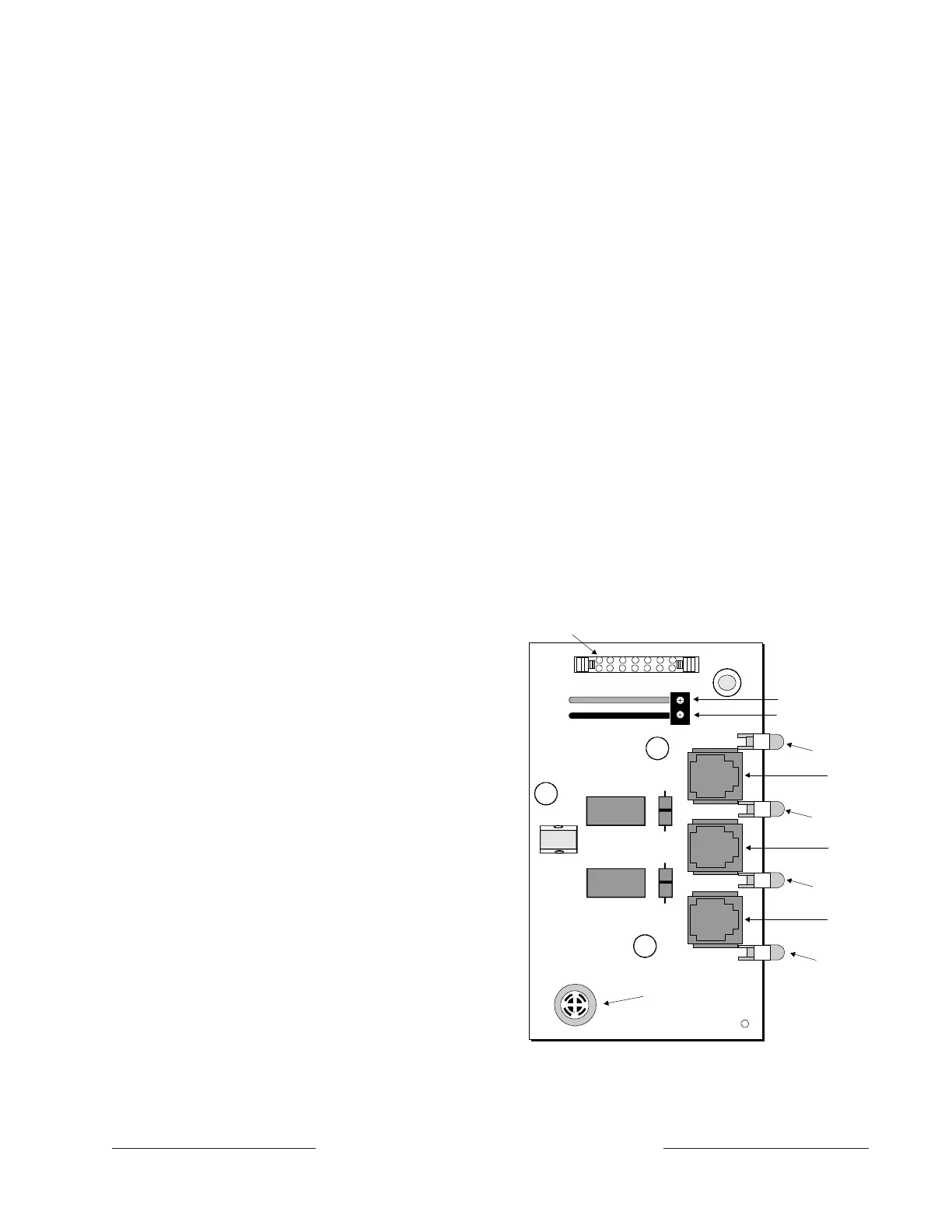
Connect to ACCESSORY
CONNECTOR (J2) with ribbon cable
Phone jack to primary
phone line - RJ31X
Phone jack to secondary
phone line - RJ31X
Phone jack to
TELCO CONNECTOR
Buzzer
Phone jack to primary
phone line - RJ31X
Green to Terminal 1
Black to Terminal 10
AC Power LED
(Green)
Primary Fail LED
(Yellow)
Secondary Fail LED
(Yellow)
Communications
Fail LED
(Yellow)
Figure 10: D928 Dual Phone Line Switcher
www.PDF-Zoo.com