D9000/D7000 Series Operation & Installation Manual
Page 44
74-07692-000-C 4/97
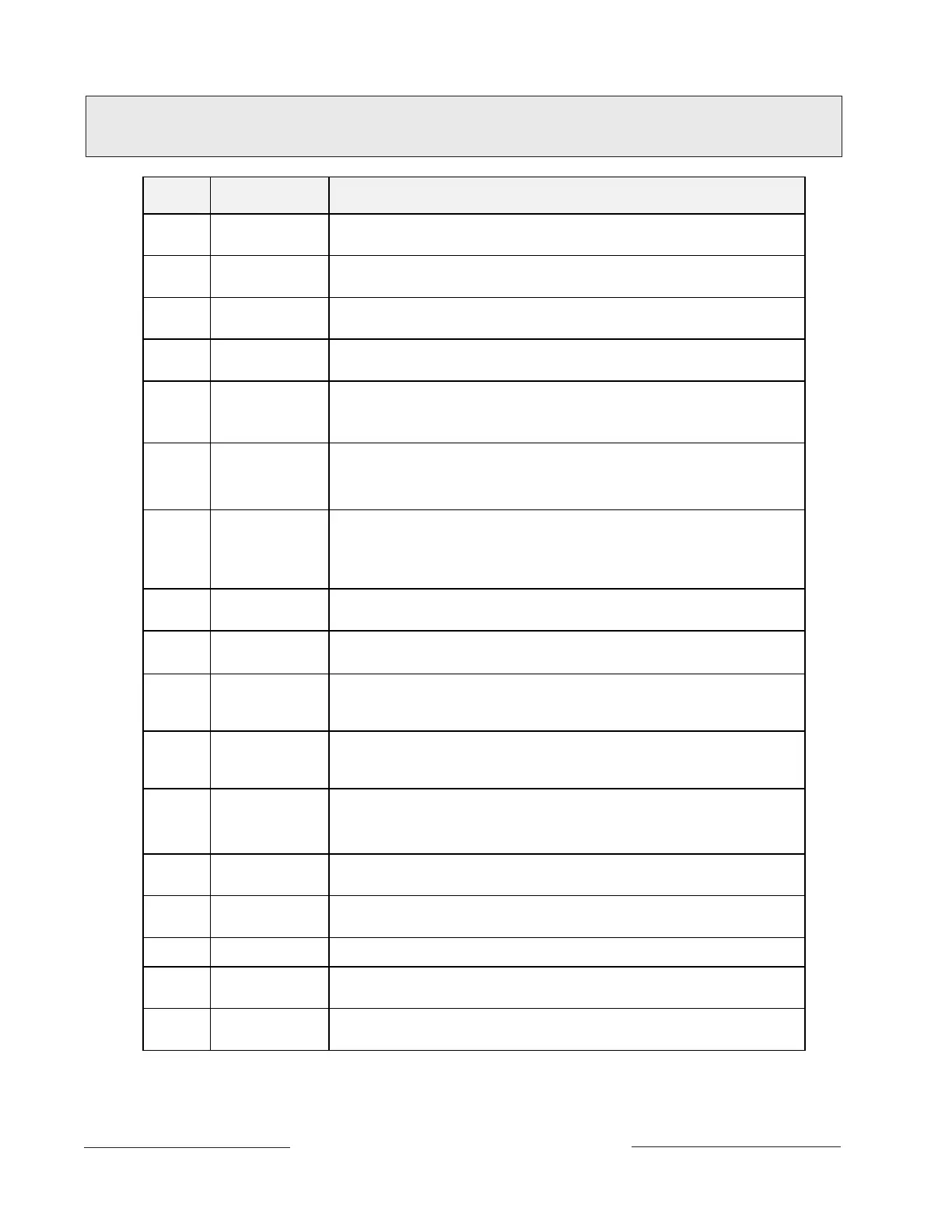
Quick Reference Terminal Description
Terminal Name Description
1, 2 CLASS 2
TRANSFORMER
Connect 16.5 VAC, 40 VA transformer for primary power supply.
3 + AUX POWER
Supplies up to 1.4A at 10.2 VDC to 13.9 VDC to powered devices. Use terminal 9
for common. Shares circuit breaker with terminal 24 and the Expansion Port (J4).
4
BATTERY
NEGATIVE ONLY
Connect 12V, 7Ah rechargeable lead acid type battery’s negative terminal (-) to
terminal 4.
5 (+)
BATTERY
POSITIVE ONLY
Connect 12V, 7Ah rechargeable lead acid type battery’s positive terminal (+).
6 (+)
+ STEADY OR
PULSED
ALARM POWER
Supplies up to 2 A at 10.2 VDC to 13.9 VDC for steady or pulsed alarm output.
Use terminal 9 for common. Programmed as Relay A.
Shares circuit breaker with terminals 7 and 8.
7 (+)
+ ALTERNATE
ALARM POWER
Supplies up to 2 A at 10.2 VDC to 13.9 VDC for steady or pulsed alarm output. Use
terminal 9 for common. Programmed as Relay B.
Shares circuit breaker with terminals 6 and 8.
D136 Plug-in Relay required:
Install a D136 in socket K3 for output at terminal 7.
8 (+)
+ SWITCHED AUX
POWER
Supplies up to 1.4 Amps at 10.2 VDC to 13.9 VDC. Use terminal 9 for common.
Programmed as Relay C
Continuous output interrupted by RESET SENSORS or alarm verification.
Shares circuit breaker with terminals 6 and 7.
D136 Plug-in Relay required:
Install a D136 in socket K1 for output at terminal 8.
9 COMMON
Terminal 9 is common for Auxiliary Power, Steady or Pulsed Alarm Power, Alternate
Alarm Power, and Switched Aux Power (terminals 3, 6, 7, and 8).
10 EARTH GROUND
Connect to earth ground. A cold water pipe or grounding rod is preferred.
Do not connect to telephone or electrical ground.
11, 13, 14,
16, 17, 19,
20, 22
ON-BOARD
POINTS
(Inputs)
Connect normally open and/or normally closed detection devices to loop wiring.
1 k
Ω
resistor required at end of loop.
12, 15, 18,
21
ON-BOARD
POINTS
(Common)
Loop returns for on-board points.
23 (-)
24 (+)
ZONEX
COMMON
ZONEX POWER+
[D9412/D9112 only] Use terminals 23 and 24 to power ZONEX modules such as the
D8125 POPEX module, the D8128C OctoPOPIT, and the D8129 OctoRelay. Shares
circuit breaker with terminal 3 and the Expansion Port (J4).
25
26
ZONEX IN 2
ZONEX OUT 2
[D9412/D9112 only] Connect ZONEX modules for points 129 to 247 and relays
65 to 128 to these terminals.
27
28
ZONEX IN 1
ZONEX OUT 1
Connect ZONEX modules for points 9 to 127 and relays 1 to 64 to these terminals.
(The D7412/D7212 uses points 9 to 75.)
29 (-) COMMON Common terminal for SDI devices
30
31
DATA BUS B
DATA BUS A
Terminals 30 and 31 are a two wire bus that drives the command centers, printer
interface, and access control modules.
32 (+) POWER +
Power for SDI devices. This separate protected power output for SDI devices is not
affected by shorts on any other terminal.
www.PDF-Zoo.com