D9000/D7000 Series Operation & Installation Manual
Page 42
74-07692-000-C 4/97
Programmer and Accessory Connections
Programmer Connector (J7)
The procedure below shows you how to connect
and disconnect the programmer. Refer to
D5200
Programmer Operation Manual
(74-06176-000)
for complete information on using the D5200
programmer.
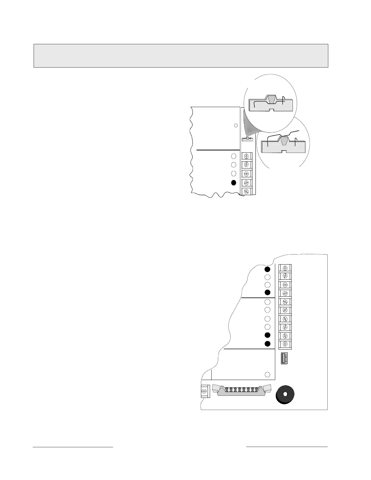
1.
Lock Reset Pin:
See Figure 19 (right) and
Locking the Reset Pin.
2. Connect the D5200 Data/Power cord into the
programmer connector (J7).
3. Perform the desired programming function
(send or receive program).
4. Disconnect the programmer.
Programmer Access Reports
If you send a program to the panel, the panel
sends a PROG ACCESS OK report ten seconds
after you exit the handler or when you disconnect
the programmer. The Diagnostic Reports prompt
in Routing must be programmed YES for this
report to be sent.
Accessory Connector (J2)
Use the Accessory Connector (J2) to connect
the panel to the D928 Dual Phone Line Switcher.
The Accessory Connector is on the bottom right
corner of the I/O board. See Figure 20. The D928
allows the panel to use two telephone lines to
transmit reports.
See
D928 Dual Phone Line Switcher
in the
Telephone Connections
section of this manual
for installation and operating instructions.
Operation Monitor
Pulses When Normal
Flickers When Ringing
32
COMMON -
31
30
29
GR N
RESET PIN
LOCKED (CLOSED)
RESET PIN
NORMAL (OPEN)
Reset Pin
Disable All Except Battery
Charging and Local Programming
DATA BUS B
DATA BUS A
POWER +
BLACK
GREEN
YELLOW
RED
FOR PROGRAMMING PANEL
FOR NORMAL PANEL OPERATION
Figure 19: Reset Pin
31
30
29
26
24
25
27
28
23
J2
ACCESSORY
CONNECTOR
PROG
CONN
COMMON
ZONEX IN 1
ZONEX OUT 2
ZONEX IN 2
ZONEX COMMON
J7
PROGRAMMER
ZONEX POWER +
ZONEX OUT 1
DATA BUS B
DATA BUS A
32
POWER +
Figure 20: Programmer and Accessory
Connections
www.PDF-Zoo.com