D9000/D7000 Series Operation & Installation Manual
Page 22
74-07692-000-C 4/97
The panel stops monitoring the phone line during
its phone line trouble response. If the response
includes sending a report, the panel does not
resume monitoring until the report is
acknowledged or it goes into communication
failure.
Bad line may test OK:
The telephone line
monitor uses voltage and current levels to test the
status of the phone line. In some instances a
given telephone line may be out of service
without affecting the voltage on the line. The
phone line monitor can not recognize this trouble
condition.
Phone Line Test Points
You can attach a telephone test set to the panel
at the TELTEST points located above the TELCO
jack on the lower left corner of the panel. See
Figure 8.
Communication Failure
After 10 attempts to reach the receiver, the panel
goes into communication failure. The panel
clears any reports in the specified Route Group.
COMM FAIL ROUTE # appears in the display at
command centers.
If you use the D928 Dual Phone Line Switcher,
the system makes a total of 10 attempts before
going into communication failure.
Ground Start
Some telephone systems require a momentary
ground input to initiate dial tone. To interface with
a ground start system, insert a plug-in relay
(D136) into socket K6/J5 and set the Phone
Monitor Select jumper to the GND START
position. Terminal 10 must be connected to an
earth ground reference.
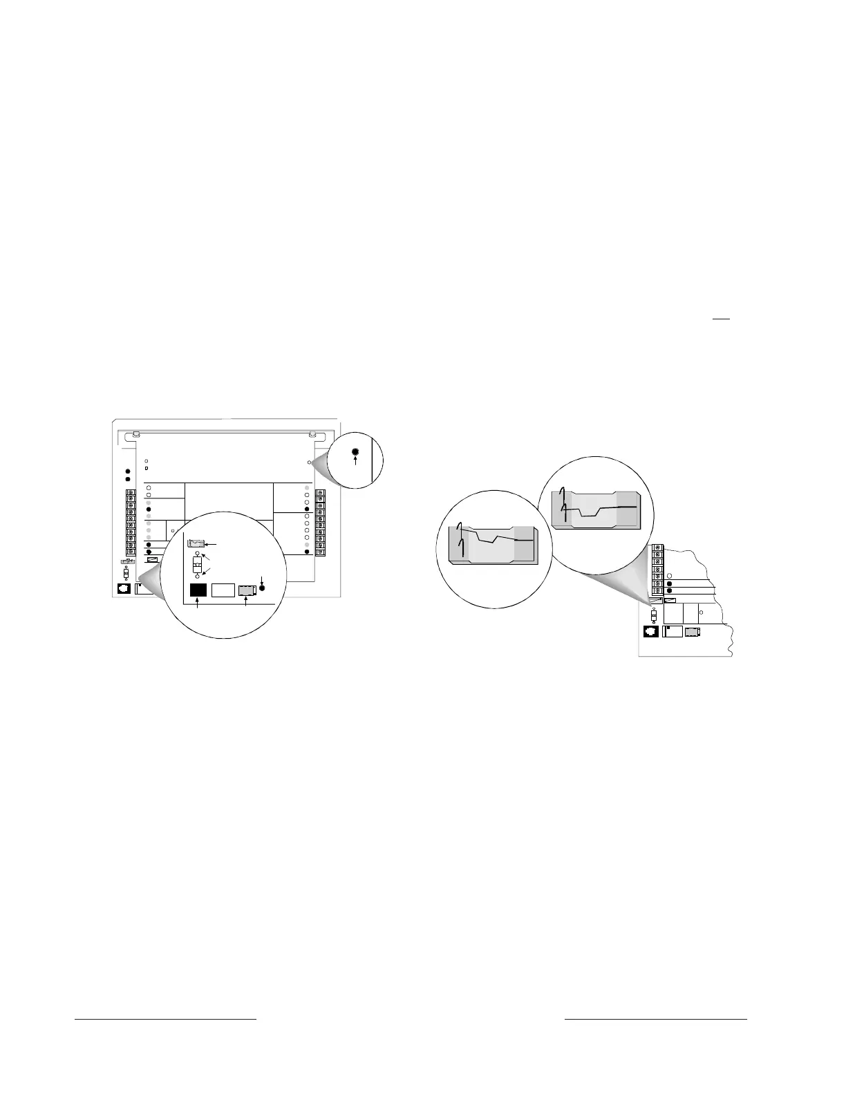
Relay Installation
Power down the system before inserting the
D136 relay into socket K6/J5. The relay socket is
in the lower left corner as shown in Figure 6. The
plug-in relay is shorter than the socket it plugs
into. You can install it in either the left or right end
of the socket.
Don’t rely on relay labeling:
You shouldn’t rely
on the labelling to install D136 relays. Check for
the side with three pins. The three pins go on the
top side.
Incorrect insertion does not damage the relay or
the panel, however the related circuits do not
function properly. A ground start relay must not
be inserted if the ground start jumper is in the
loop start position (see below).
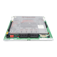
Phone Monitor Select Jumper
The Phone Monitor Select jumper is above the
TELCO connector and TELTEST point at the
lower left corner of the panel. Set it in the ground
start position. See Figure 9.
Figure 8: Telephone Connections
5
9
10
1
2
Low Bat ter y
LE Ds O ff W he n No r m a l
EARTH GROUND
COMMON
CL ASS 2 T RAN SFO RME R
16.5 VAC 40 VA 60 HZ
Part No. D1640
Internally Fused - D o Not Short
R eq uire s Unswit ched Ou tle t
Do Not Share With Other Equipment
+ AUX POWER
BATT ERY N EGA TI VE ONL Y
Maximum Char
in
Current 1.4 Amps.
PHONE MONITOR SELECT
Loop S tart
Ground S tart
TELCO
CORD
PHONE
LED
ON WHE N
COMMUNI CATING
OFF WHEN IDLE
Requir es
Rela
#D136
ON-BO ARD POINTS
1.0K Resis tor
Required at End of Line
Ω
VOLTAGE RANGES
Open 3.7 - 5.0VDC
Normal 2.0 - 3.0VDC
Sho rt 0.0 - 1.3V DC
PERIPHERAL DEVICE WIRING
ZONEX OUT 1
ZONEX I N 1
ZONEX OUT 2
ZONEX I N 2
ZONEX P OWER +
ZONEX COMMON
Op erat ion Mo nito r
Pulses When Normal
Flic k ers W h en Ri n
in
PROG
CONN
RED
YELLOW
GREEN
BL ACK
17- 0 582 3-0 02
32
POWE R +
DATA BUS A
COMMON
RED
GROUND
START
YEL
RED
Reset Pin
Disabl e All Except Batter
Char
in
And Pro
rammi n
GRN
STEADY OR
PULSE
+
Char
in
Status
N.F.P.A.
Style 3.5
Si
nal in
Line
Circuits
12
15 18 2113
11
14 16 17 19 20 22
PROGRAMMABLE
ALARM OUTPUTS
Terminals
&
Requir e
Op ti o na l
D136 Rela y
in J1 & J9
7
Point 1 P oint 2 Point 3 Poin t 4 P oint 5 Point 6 Point 7 Point 8
DATA BUS B
29
31
30
24
23
28
27
26
25
BATTERY POSITIVE ONLY
+ ALTERNATE
SWITCHED
AUX POWER
+
6
7
8
8
3
4
Ba t te r y
GRN
OPERATOR
MONITOR LED
(GRE EN)
M
PHONE LINE
TEST POINTS
PHONE LED
(RE D )
PHONE MONITOR
SELECT JUMPER
TELCO CORD
CONNECTOR (J3)
GROUND START
RELAY (K6)
8
9
10
RED
COMMON
Ground Start
Loop S tar t
TELCO
CORD
M
PHONE MONITOR SELECT
+ SWITCHED
AUX POWER
EARTH GROUND
GROU ND
START
Re
uires
Rela
#D 13 6
in J5
LOOP START
POSITION
GROUND START
POSITION
Figure 9: Phone Monitor Select
Warning: Ground start not for use in NFPA
applications.
You can not use ground start
telephone systems for NFPA Central Station
Protective Signaling or Remote Station
applications.
D928 Dual Phone Line Switcher
Description
The optional D928 Dual Phone Line Switcher
allows the panel to transmit reports over a
secondary phone line when the primary phone
line is faulted. The panel monitors both lines. If a
signal is generated and the panel senses that the
primary phone line is bad, then it will attempt to
use the secondary phone line to send the
message. If trouble is detected, the panel keeps
the faulty phone line in memory.
www.PDF-Zoo.com