D9000/D7000 Series Operation & Installation Manual
Page 36
74-07692-000-C 4/97
Installation
You can install the D811 in the enclosure with the
panel (see Figure 2) or in an adjacent enclosure
not more than 5 feet from the panel. Use 16 to 22
AWG wire.
Follow the procedure below to install D811
modules in the enclosure with the panel.
1. Align the D811 module with any of the four
mounting locations in the enclosure. See
Figure 2.
2. Use the screws provided with the module to
secure it in the enclosure.
Use the D137 Mounting Bracket to install D811
modules in enclosures with no module mounting
locations available.
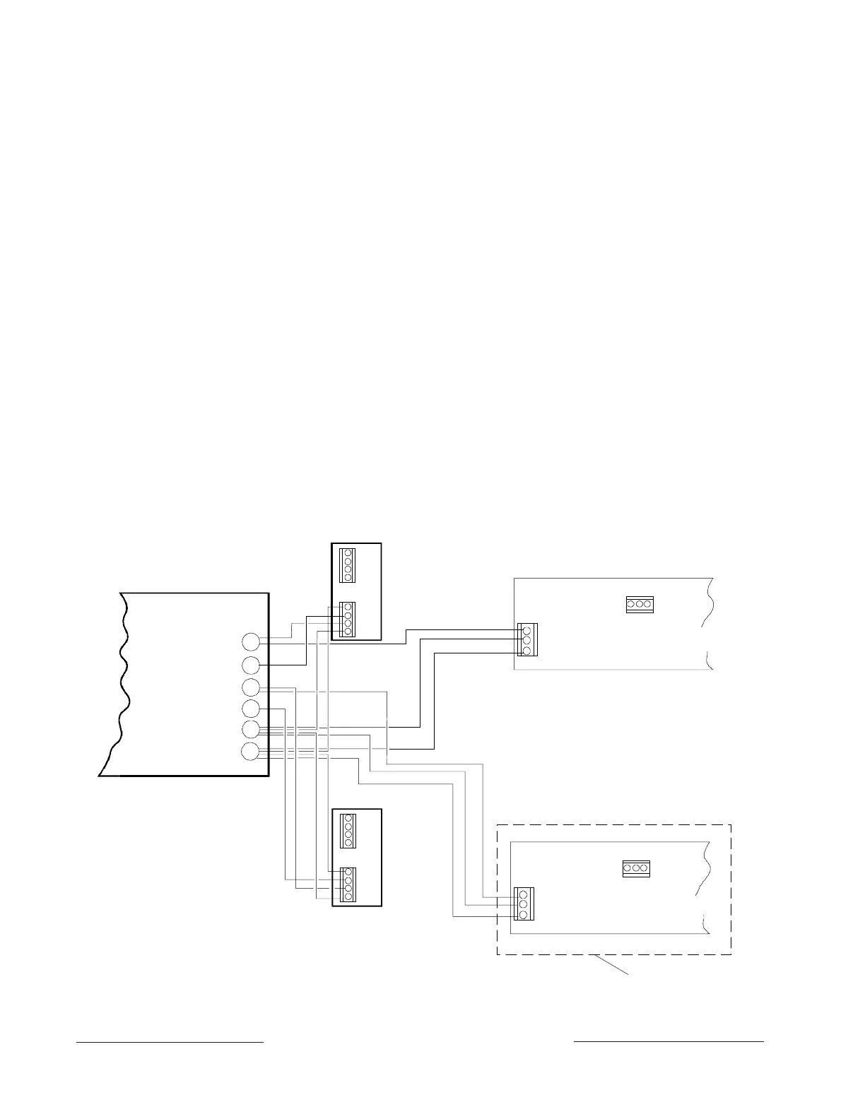
Wiring Connections
Power down the panel to connect D811 modules
as shown in Figure 16. Note that the D811 for
relay number 53 connects to ZONEX 1. The D811
for relay number 117 connects to ZONEX 2 on
the D9412/D9112.
Figure 16: D811 Module Wiring
5
GND
D8125
POPEX
(-)
(-)
(+)
(+)
GND
OUT
IN
AUX
ZONEX OUT 1
ZONEX IN 1
ZONEX OUT 2
ZONEX IN 2
ZONEX COMMON
Control/Communicator
Panel
28
27
26
25
24
23
(-)
(-)
(+)
(+)
AUX
DA TA
D811 FOR RELAY NUMBER 117
5
GND
AUX
DA T A
D811 FOR RELAY NUMBER 53
ZONEX POWER +
GND
OUT
IN
AUX
D8125
POPEX
D9412/D9112 Only
www.PDF-Zoo.com