Radware Alteon Installation and Maintenance Guide
Alteon Application Switch Platforms
32 Document ID: RDWR-ALOS-V2815_IG0203
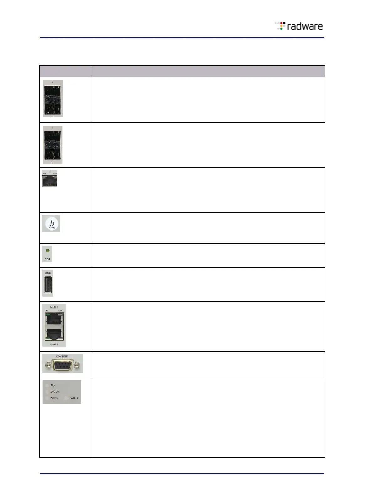
Table 5: Alteon Application Switch 5224 and 5224 XL Front Panel
Feature Label/Description
2 (Two) Gigabit Ethernet (10GbE) ports for traffic or in-band management. The
platform supports four XFP ports.
LEDs:
• ACT—flashing indicates activity.
• LINK—green indicates 10GbE.
16 (Sixteen) SFP GbE ports for traffic or in-band managment. The platform
supports four SFP ports.
LEDs:
• ACT—flashing indicates activity.
• LINK—green indicates 1000 Mbit/s.
8 (Eight) RJ-45 GbE ports for traffic or in-band management. The platform
supports eight GbE ports.
LEDs:
• ACT—flashing indicates activity.
• LINK—green indicates 1000 Mbit/s. Yellow indicates 10 or 100 Mbit/s.
Power button. Turns power on and off. Pressing the button for 1 to 4 seconds
causes a graceful shutdown of the system, thus preserving system integrity.
Pressing the button for more than four (4) seconds causes the hardware to
power down.
Reset button. Resets the device.
USB port for recovery.
Management port. The MNG 1 port is an RJ-45 10/100/1000 Ethernet port,
which is for management only. The MNG 2 port is currently non-operational.
LEDs:
• ACT—flashing indicates activity.
• LINK—green indicates 1000 Mbit/s. Yellow indicates 10 or 100 Mbit/s.
RS-232 DE-9 port for out-of-band management.
Status LEDs:
• FAN—green indicates nominal operation. Red indicates that one or more
fans is not operating.
• SYS OK—green indicates nominal operation. Red indicates that the device is
booting. Red or alternating red and green indicates a warning (for example,
the temperature is high, but still in the allowed range).
• PWR_1 and PWR_2—green indicates nominal operation. Red indicates that
one of the two power cables is not supplying power or that one of the power
supplies is malfunctioning. When the LED is red, a qualified service person
should immediately check the power source and the power supply.
 Loading...