8.2.3 LAN Port
The LAN 10/100BaseT interface terminates in an 8‐pin RJ‐45 connector, wired as shown in
the following table.
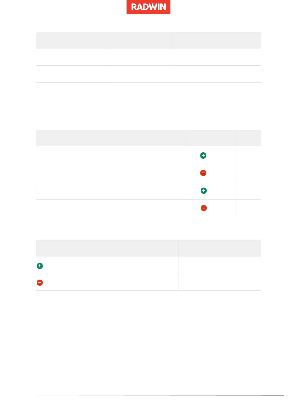
Fast Ethernet Connector Pinout
8.3 Setting Antenna Parameters
8.3.1 Antenna Issues
Before proceeding to the details of antenna installations, the following background
information should be considered.
8.3.2 About Single and Dual Antennas
Each RADWIN 2000‐Plus Family ODU is made of two radio transceivers (radios). The radios
make use of algorithms that utilize both Spatial Multiplexing and Diversity resulting in
enhanced capacity, range and link availability. The number of antennas used is determined
by user configuration and by automatic system decisions, explained below.
 Loading...