10 | Gas connection for gas devices
68 / 84 80.06.083_iCombi Pro-iCombi Classic_IM_V01_en-US
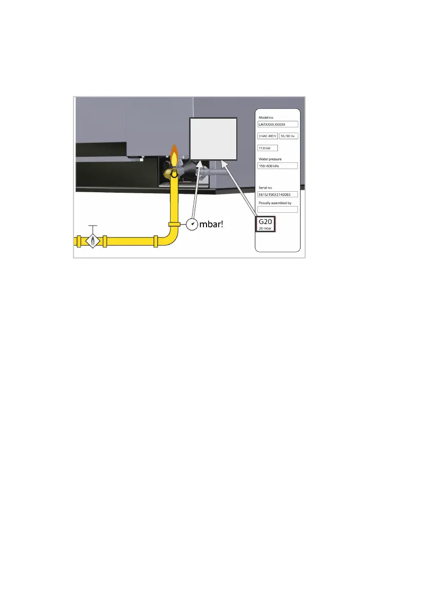
Requirements for gas type and gas pressure
n
Check that the ex-works gas setting on the device matches the actual con-
ditions for the local gas connection.
n
The gas type and the dynamic connection pressure set in the device must
match the specifications on the type plate.
n
If the line pressure deviates from the connection flow pressure of the de-
vice, contact your gas supply company.
n
Observe the regulations of the local gas supply company.
Requirements for gas supply and gas lines
n
The flue gas analysis may only be carried out by a technician authorized by
the manufacturer. The flue gas analysis must be carried out before com-
missioning.
n
The gas connection may only be carried out by a locally approved gas in-
staller.
n
The gas connection line must be designed for the nominal heat load speci-
fied on the type plate.
n
The gas supply and gas distribution in the device must be checked for
leaks using a suitable gas leak detector.
n
The cross-section of the gas line must be designed for the maximum con-
nected power of all consumers, at least ¾ inch.
n
A gas shut-off valve must be installed upstream of each device.
n
All on-site connection parts must be tested in accordance with DIN-
DVGW (the local gas supply companies).
n
The gas line can be connected to a gas socket.
n
A connection with internal thread is required to connect the gas line.
n
The device must be secured against slipping.
n
For values of undiluted CO greater than 174.7 mg/m³ [150 ppm] for hot
air and greater than 465.8 mg/m³ [400 ppm] for steam, the burner setting
must be checked by a company-trained and certified technician in accor-
dance with the setting instructions, and reset if necessary. Subsequently, a
flue gas analysis must be carried out by the technician.
n
Observe the maintenance instructions for gas components.
n
The gas installation must comply with CGA-B 149.1 natural gas regula-
tions or CGA-B 149.2 propane gas regulations.