1568233 46-R3
ROUBLESHOOTING
T
2.4-3 Load Cells
NOTE: Cascade recommends using Debug Mode first.
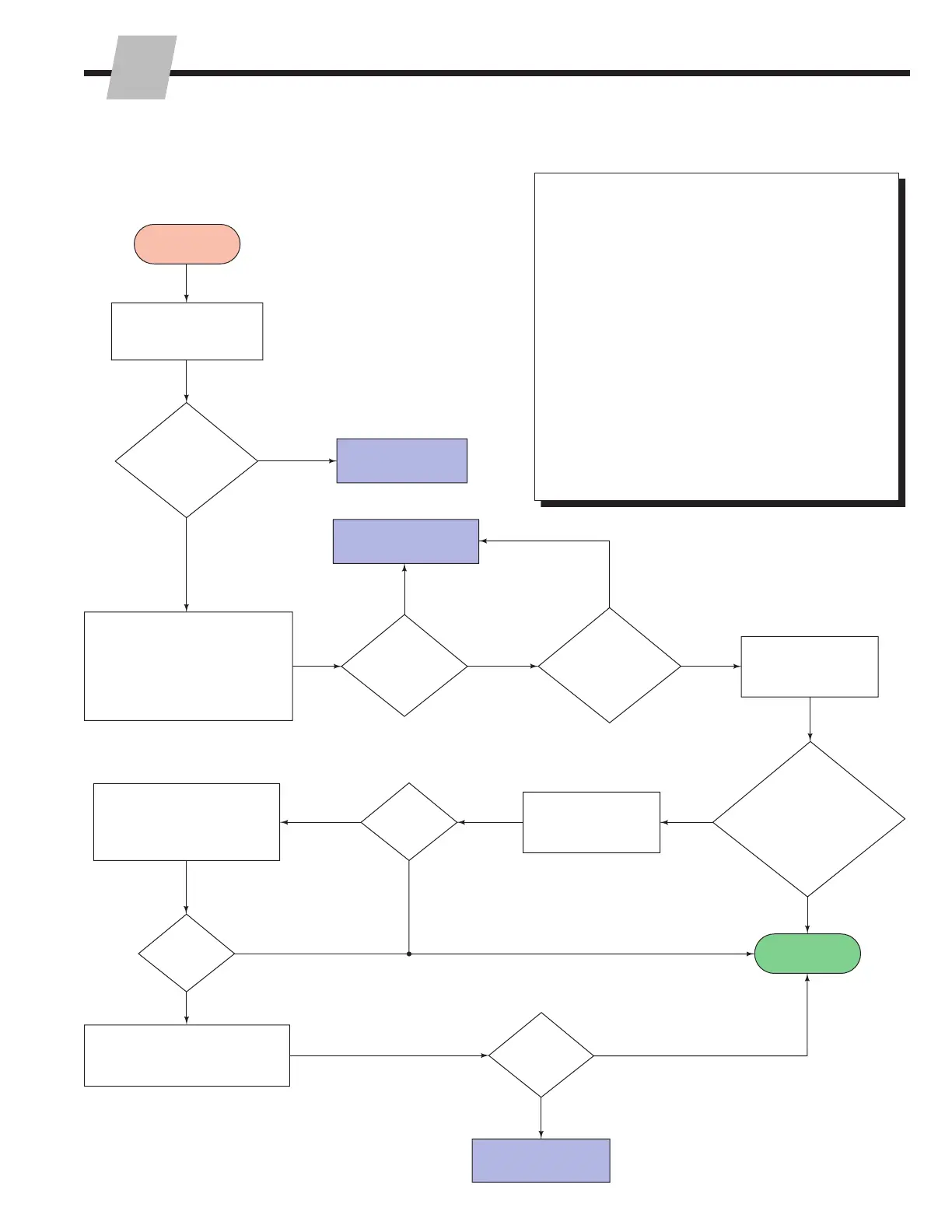
If further troubleshooting is required, follow this flow chart.
Testing Individual Load Cells –
With a load cell disconnected from the iFork system:
• Measure resistance. The resistance between
the power + (red) and signal + (green) should
be equal, within 2 ohms, of the resistance
between power - (black) and signal - (white). The
resistance between the wires and load cells should
be infinite.
OR
• To determine if one load cell is the problem,
connect each load cell to the display (using it as
a voltmeter) and compare the values shown for
each load cell. The separate values should be
close in value. If one value differs from the other
by a considerable amount, the load cell should be
replaced. Verify that the cables are not damaged.
Complete
Display
still shows
an error
Display
still shows
an error
Display is
instable
With or
without a load
display show over
or underload error message
and system will not
reset to zero
The difference
is larger then 1/2
graduation
Each load
cell gives the
same weight
The difference
between each
cell is large
Verify display is not creating
the problem. Replace the
touch panel and then
calibrate.
Check load cells separately.
Refer to "Testing Individual
Load Cells".
Place a weight on each
of the bolts of the iFork
assemblies
Calibrate load cells.
Refer to Service
Section 3.1.
Calibrate load cells.
Refer to Service
Section 3.1.
Load cell is not the
problem
Dismantle the iFork assembly.
Place capscrews in the
assembly holes of the load
cells. Balance a test weight that
is 1% of their capacity of each
load cell on the capscrews.
Check display, refer
to Section 2.4-4
Check iFork assembly,
refer to Section 2.4-1.
YES
YES
YES
YES
YES
YES
YES
NO
NO
NO
NO
NO
NO
NO
Start


 To Next Page