CHAPTER 4
18 SCS 440 Serial Interface Installation & Service Manual
FIGURE 6. Switch Assembly Installed
NOTE: The switch assembly does not need to pivot with the wheel.
4. Loosely mount the switch assembly to the wheel axle with the supplied hardware, positioning it so that as the
wheel rotates, the magnets pass across the center of the switch assembly.
• Clearance between the magnets and the switch assembly must be 1/4” - 1” [6 mm - 25 mm].
• Make sure the machine’s wheels can be turned to the extremes in each direction without the magnets
coming in contact with the switch assembly.
5. Tighten the mounting hardware to secure the switch assembly.
6. Secure the switch assembly cable to the axle with zip ties.
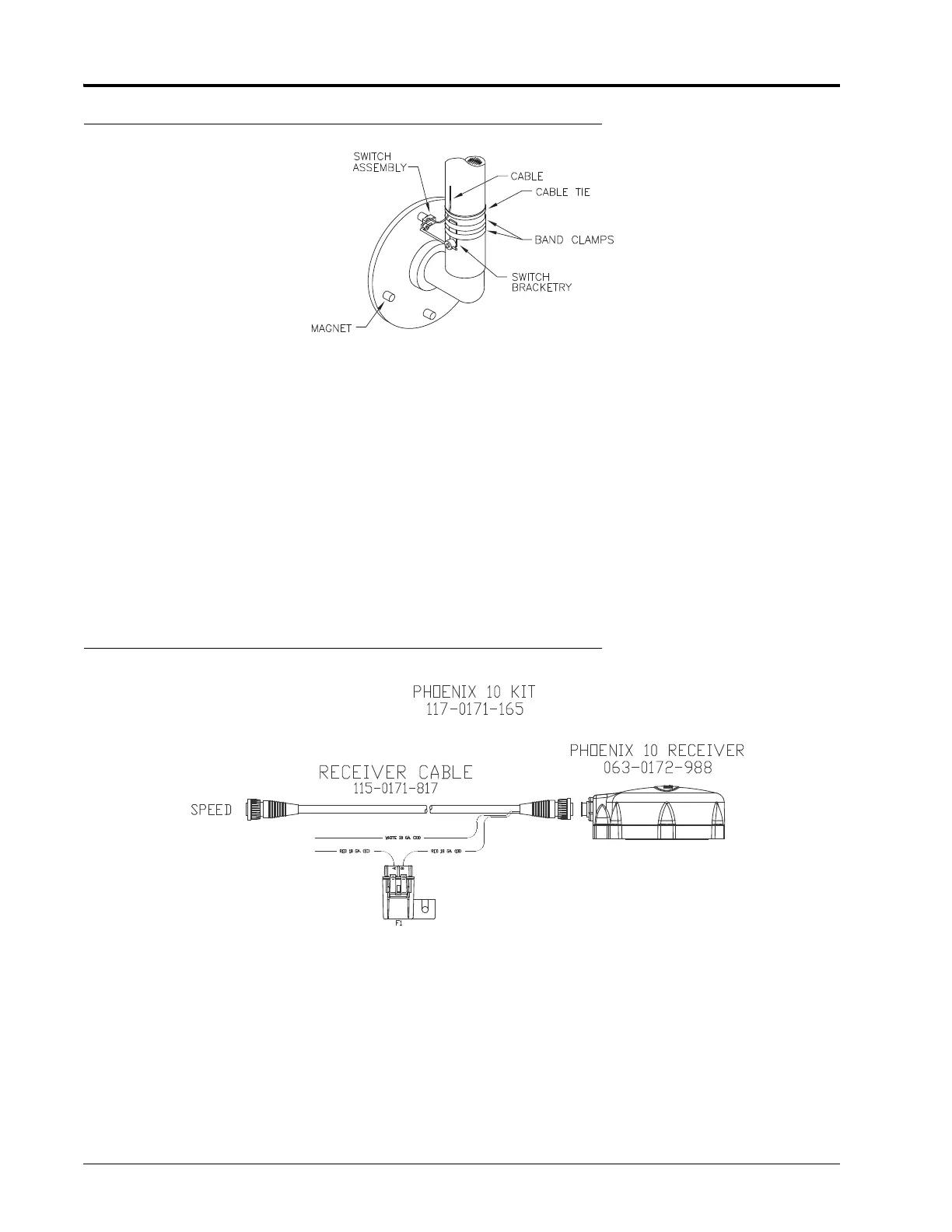
PHOENIX 10 GPS SPEED SENSOR
FIGURE 7. Phoenix 10 Speed Sensor Installed
NOTE: The Phoenix 10 is powered by a 9 - 16 VDC negative ground system.
1. Turn off all equipment on the machine to avoid interference with the speed sensor setup.
2. Apply power to the speed sensor by connecting the white wire to a clean ground and the red wire to a clean
switched power source.
 Loading...