CHAPTER
6
Manual No. 016-0159-822 Rev E 43
CHAPTER 6
INITIAL SYSTEM SETUP AND
TESTING
INITIAL SYSTEM SETUP
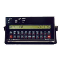
After all components of the system have been installed and the console has been programmed, the SCS 440 is
ready to be set up. Complete the following steps to set up the SCS 440 system.
NOTE: This procedure applies only to applications of 3 GPM [11 lit/min] or greater. For flow less than 3 gpm
[11 lit/min] refer to the Alternate Bypass Line System Setup section on page 44 for the alternate
bypass line setup procedure.
1. Fill the tank with water only.
2. If a centrifugal pump is used, proceed to the next step. If a positive displacement pump is used, open the
pressure relief valve (PRV).
3. Switch the Rate switch to MAN.
4. Switch the Power switch to ON.
5. Verify that the BOOM CAL, SPEED CAL, METER CAL, VALVE CAL, and RATE CAL values have been entered
correctly into the console.
6. Press the SELF TEST button.
7. Enter the machine’s normal operating speed.
8. Run the pump at the normal operating RPMs.
9. If a centrifugal pump is used, proceed to the next step. If a positive displacement pump is used, set the PRV to
65 psi [450 kPa].
10. Verify that the boom valves operate and that no nozzles are plugged using the boom ON/OFF switches.
11. Switch all boom ON/OFF switches to the ON position.
12. Hold the FLOW CONTROL switch in the INC position until the pressure is at its maximum to ensure that the
control valve is fully open.
13. Verify the RATE and maximum pressure.
NOTE: The pressure gauge is not supplied. A pressure gauge MUST be installed to properly monitor the
system.
14. Adjust the agitator line hand valve until the desired agitation is reached.
15. Verify that the maximum pressure is still present.
16. Hold the FLOW CONTROL switch in the DEC position until the pressure is at its minimum to ensure that the
control valve is fully closed.
17. Verify RATE and minimum pressure.
NOTE: If the RATE and minimum pressure cannot be achieved, consider modifying the plumbing into the
alternate bypass plumbing system configuration. Refer to the Alternate Bypass Line System Setup
section on page 44.
 Loading...