CHAPTER 7
48 SCS 440 Serial Interface Installation & Service Manual
d. Loosen the turbine stud 1/3 of a turn. The turbine should spin freely.
5. Reassemble the flow meter.
6. Use a low pressure (5 psi/34.5 kPa) burst of air to verify that the turbine spins freely. If there is a drag, loosen
the hex stud on the bottom of the turbine hum 1/16 of a turn until the turbine spins freely.
7. Store the flow meter in an area that prevents it from freezing.
TESTING FLOW METER CABLES
1. Disconnect the cable from the flow sensor.
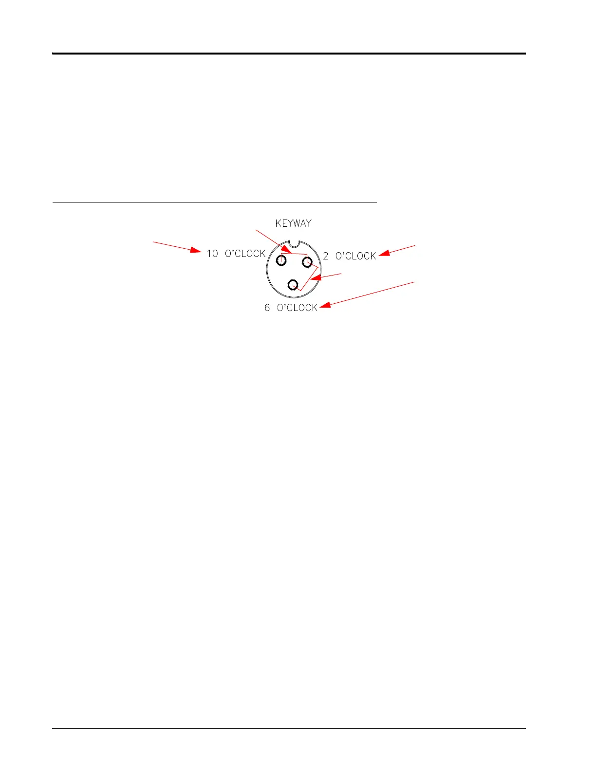
FIGURE 1. Flow Sensor Connector Cable Connection
NOTE: If a +5 VDC voltage reading is not present, disconnect the speed sensor cable. If the flow reading is
restored, refer to the Testing Speed Sensor Extension Cables section on page 49 to test the speed
sensor extension cables.
1. Enter a METER CAL value of 1 into the console.
2. Press the TOTAL VOLUME button.
3. Place the RATE 1/RATE 2/MAN switch in the MAN position.
4. Turn the boom switches ON.
5. Create a short between the ground and signal sockets by inserting a small jumper wire or paper clip into both
sockets simultaneously. Each time contact is made, the TOTAL VOLUME reading should increase in increments
of 1 or more. If the TOTAL VOLUME does not increase:
a. Remove the section of cable closest to the console.
b. Repeat the ground-signal short test.
• If the TOTAL VOLUME does not increase, replace the defective cable and repeat the ground-signal
short test.
• If the TOTAL VOLUME increases, replace the flow sensor.
6. Perform voltage checks as illustrated in the figure above.
IMPORTANT: Re-enter the original METER CAL figure after testing is complete.
RECALIBRATING THE FLOW METER
NOTE: This procedure should be performed when the tank is filled with water, not chemicals.
1. Enter a METER CAL value of 10 [38] into the console.
2. Enter a TOTAL VOLUME value of 0 into the console.
3. Turn OFF all booms.
4. Remove a boom hose and place it into a calibrated 5 gallon [19 liter] container.
5. Turn ON the boom switch for the boom hose that was removed.
Ground
Signal
Power
+5 VDC
+5
 Loading...