5
Manual No. 016-0159-822 Rev E 29
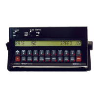
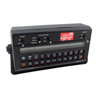
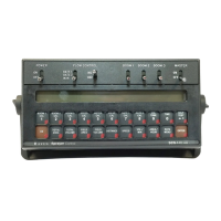
CONSOLE PROGRAMMING AND CALIBRATION
BUTTON DEFINITIONS
CALIBRATION BUTTONS
The calibration buttons are used to enter data into the console when calibrating the system. Refer to the table
below for the button names and functions.
FUNCTION BUTTONS
The function buttons are used to display the data on a particular aspect of the application. Refer to the table
below for the button names and functions.
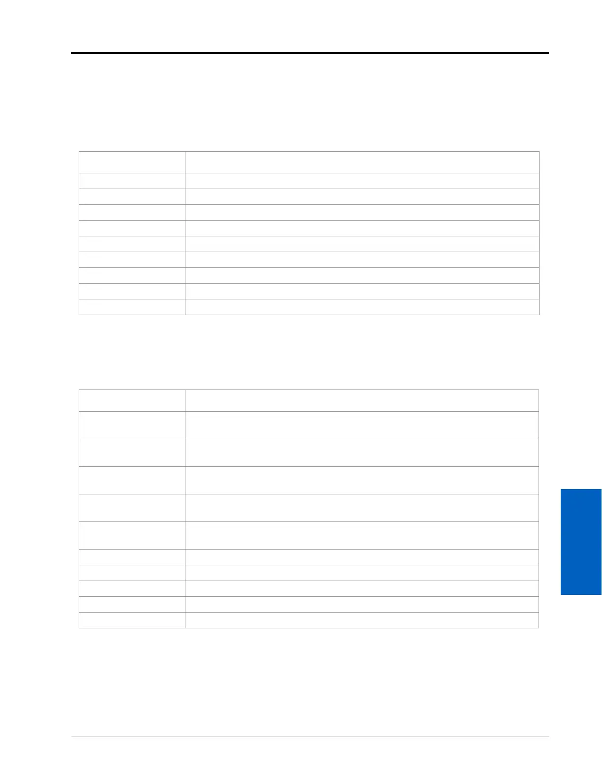
Button Name Function
BOOM CAL 1 Length of boom section 1.
BOOM CAL 2 Length of boom section 2.
BOOM CAL 3 Length of boom section 3.
SPEED CAL Determined by speed sensor.
METER CAL Meter calibration number.
VALVE CAL Valve response time
RATE 1 CAL Target application rate.
RATE 2 CAL Target application rate.
TIME 24 hour clock (military time).
Button Name Function
TOTAL AREA
Displays total area applied. To zero out this figure, press ENTER, 0, then ENTER in
this menu.
TOTAL VOLUME
Displays total volume applied. To zero out this figure, press ENTER, 0, then ENTER
in this menu.
FIELD AREA
Displays field area applied. To zero out this figure, press ENTER, 0, then ENTER in
this menu.
FIELD VOLUME
Volume applied to the field. To zero out this figure, press ENTER, 0, then ENTER in
this menu.
DISTANCE
Displays distance traveled. To zero out this figure, press ENTER, 0, then ENTER in
this menu.
SPEED Displays the vehicle’s speed.
VOL/MIN Displays the volume per minute applied.
AREA/HOUR Calculates the total area covered per hour at the present speed (not an average).
DATA MENU Used for data logging and variable rate commands.
SELF TEST Displays data after selecting volume rate, speed sensor type, or valve type.
 Loading...