4
Manual No. 016-0159-822 Rev E 19
INSTALLATION
FLOW METER INSTALLATION
MOUNT THE FLOW METER
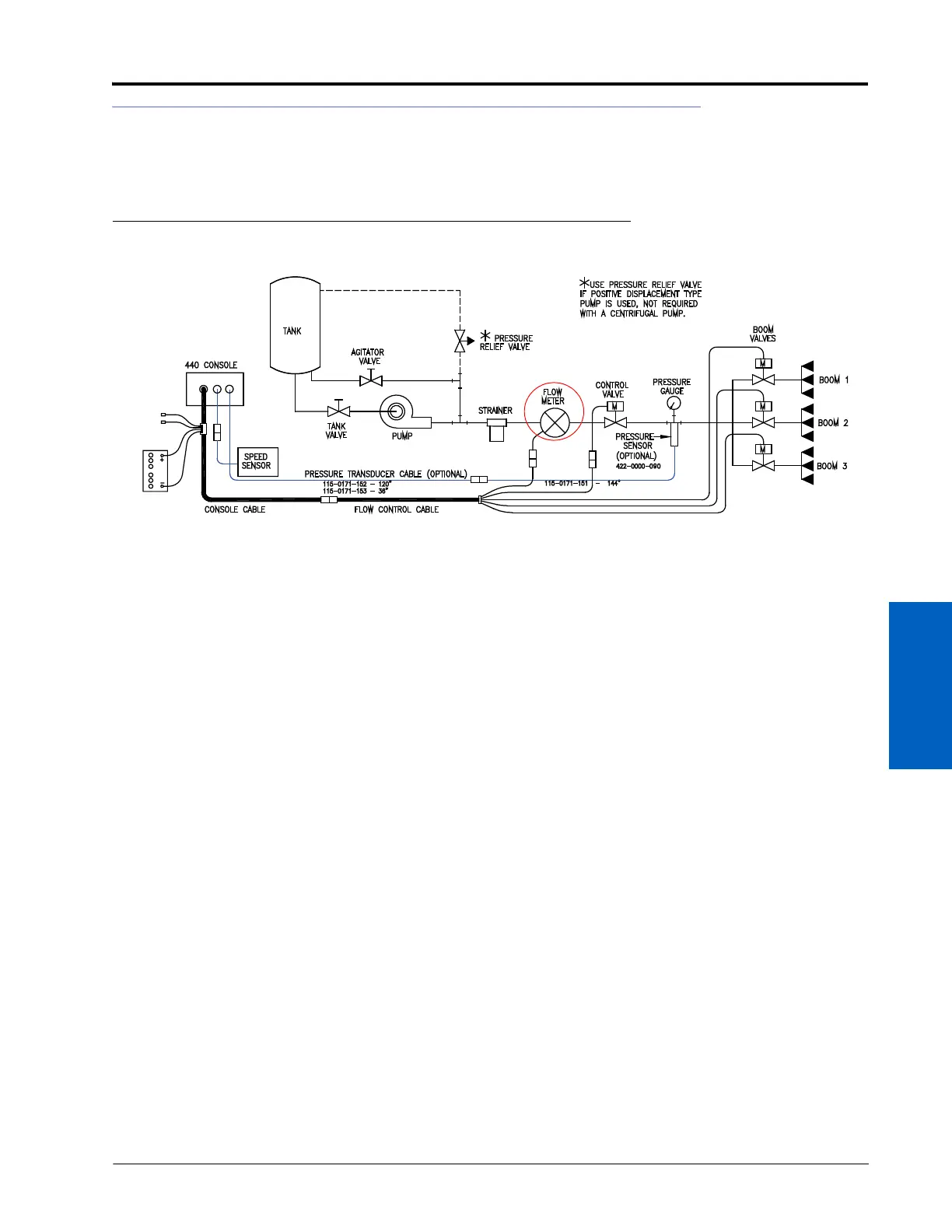
FIGURE 8. Flow Meter Installation Diagram
NOTE: All flow through the flow meter must go to the boom sections only. Ensure there are no return,
agitation, or sparge lines to the tank or pump after the flow meter.
1. Mount the flow meter in the area of the boom valves (horizontal to the ground) using the supplied bracket.
Refer to the figure above.
• Allow a minimum of 7-1/2” [20 cm] of straight hose on the inlet of the flow meter.
• The bent radius of the hose on the outlet of the flow meter should be gradual.
• The flow must be in the direction of the arrow on the flow meter.
2. Connect the female 3-pin connector of the flow control cable to the male flow meter connector.
INSTALL THE PRESSURE TRANSDUCER - OPTIONAL
1. Install the pressure transducer (P/N 422-0000-090) and pressure transducer cables (P/N 115-0171-152, 115-0171-
153, and 115-0171-151).
2. Verify that the pump is turned off and there is 0 psi/kPa of pressure in the lines.
3. Press the DATA MENU button.
4. Enter 0 as the Cal Pressure value.
NOTE: When the system is operating, the system psi/kPa will be displayed when the SPEED or VOL/MIN
button is pressed.
 Loading...