CHAPTER 7
50 SCS 440 Serial Interface Installation & Service Manual
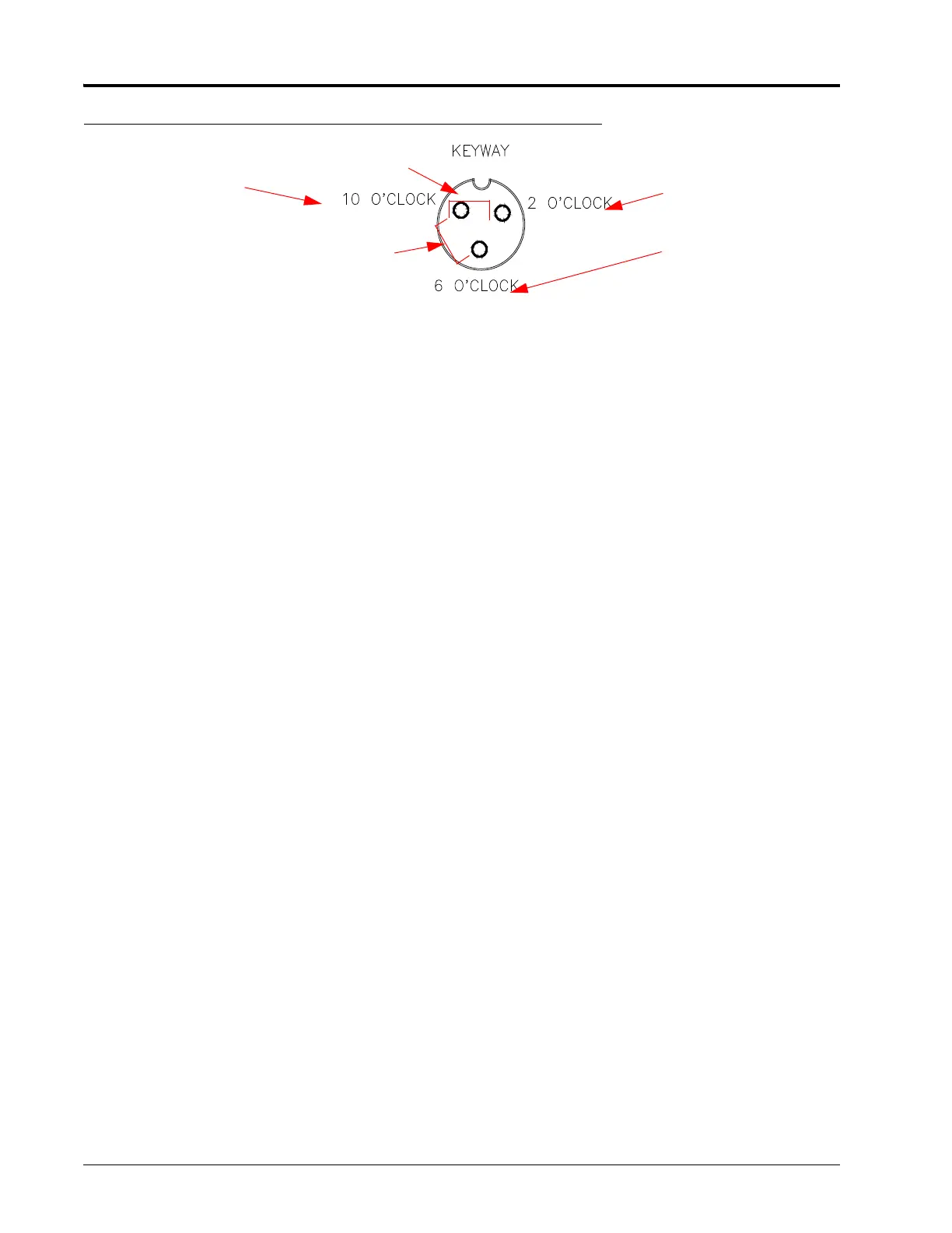
FIGURE 2. Speed Sensor Connector Cable Connection
NOTE: If a +5 VDC voltage reading is not present, disconnect the flow sensor cable. If the speed reading is
restored, refer to the Testing Flow Meter Cables section on page48 to test the flow meter cables.
If the speed system is a radar-type system, the voltage between the 10 o’clock and 2 o’clock positions
may read +12 VDC.
1. Enter a SPEED CAL value of 9999 into the console.
2. Press the DISTANCE button.
3. Create a short between the ground and signal sockets by inserting a small jumper wire or paper clip into both
sockets simultaneously. Each time contact is made, the DISTANCE reading should increase in increments of 1 or
more. If the DISTANCE does not increase:
a. Remove the section of cable closest to the console.
b. Repeat the ground-signal short test.
• If the DISTANCE does not increase, replace the defective cable and repeat the ground-signal short
test.
• If the DISTANCE increases, replace the speed sensor.
4. Perform voltage checks as illustrated in the figure above.
IMPORTANT: Re-enter the original SPEED CAL figure after testing is complete.
Power
Signal
Ground
+5 VDC
+5 VDC
 Loading...