3
Manual No. 016-5034-004 21
Hydraulic System Installation
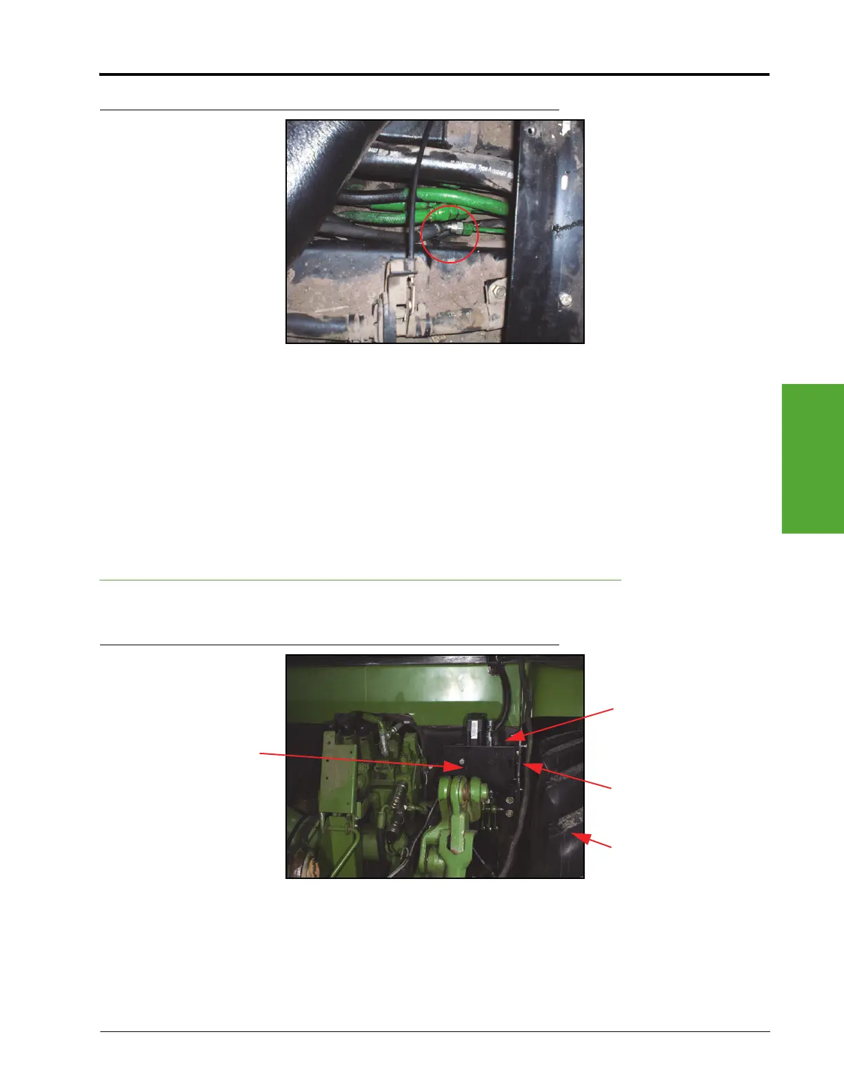
FIGURE 11. Supplied Hydraulic Hose Installed on Machine’s Load Sense Hose
5. Install a -4 ORFS M/M straight adapter fitting (P/N 214-1000-268) on the end of the machine’s load sense
hose.
6. Install the 45° end of the supplied hydraulic hose (P/N 214-1000-762) on the installed adapter fitting.
7. Label the straight end of the installed hydraulic hose “LSPV.”
Note: The installed hydraulic hose will be connected to the SmarTrax valve (P/N 334-0003-088) later in
the installation procedure.
8. Route the installed hydraulic hoses to the installed universal bracket (P/N 107-0171-578) mounting location.
Mount the SmarTrax Valve
FIGURE 12. SmarTrax Valve Installed on Universal Mounting Bracket
1. Install the SmarTrax valve (P/N 334-0003-088) on the valve mounting bracket (P/N 107-0171-907) using
four 5/16”-18 UNC x 7/8” hex bolts (P/N 311-0052-104) and four 5/16” split lock washers (P/N 313-1000-
019).
Right Rear Tire
Universal Mounting
Bracket
(P/N 107-0171-578)
SmarTrax Valve
(P/N 334-0003-088)
Valve Mounting Bracket
(P/N 107-0171-907)
 Loading...


