4
Manual No. 016-5034-004 27
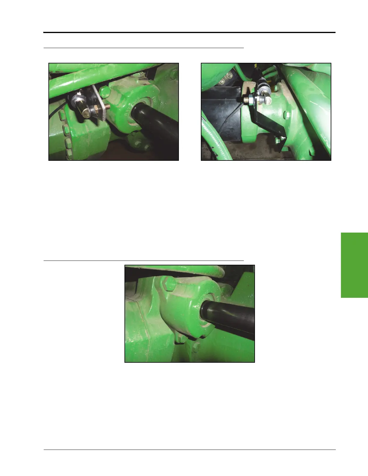
Wheel Angle Sensor Installation
FIGURE 4. Base-End of Sensor Installed on the Machine
4. Single cylinder models only - Install three 0.406” ID x 0.812” OD x 0.065” thick washers (P/N 313-2300-014)
on the stud mount of the linear sensor to offset the sensor from the base mounting bracket.
5. Secure the base-end of the WAS (P/N 063-0181-017) to the base mounting bracket using one washer (P/N
313-2300-014) and one M10 x 1.5 nylon insert lock nut (P/N 312-4000-208).
Note: The rod-end of the sensor should point toward the left tire.
Note: If the cylinder end cap bolts are recessed as shown in Figure 5 below, mount the base end to the
hole that is farthest from the bend. If bolts are not recessed, use the hole that is closest to the
bend.
FIGURE 5. Recessed End Cap Bolts
Single Steering Cylinder Models
Dual Steering Cylinder Models
 Loading...


