4
ST5000 Plus SailPilot Owner’s Handbook
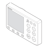
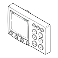
2.2 Display layout
The following illustration shows all the elements, together with a brief
description, that make up the ST5000 Plus autopilot LCD display.
Rudder or Steer Direction Indicator
• The bar graph at the bottom of the display is normally a rudder bar.
If it has been set as a direction-to-steer indicator, the display depends
on the current mode, as follows:
Mode Bar
Standby Rudder bar for systems with a rudder reference transducer
Auto Heading error bar
Track Cross track error (XTE) bar, in 0.02 nm increments
Vane Wind angle error bar
• If neither distance units (nm or SM) is displayed, the distance is in
Km.
136_3c02.p65 14/06/99, 10:164