V1.0 Raytools AG © Copyright 19 |24
www.raytools.ch
BS06K SERIES 6kW All-In-One Smart Laser Cutting Head-User Manual
4 Beam Alignment and Zero Focus Correction
4.1 Beam Alignment
Cutting quality in a great extent depends on whether the lens is in the middle. If the lens is not in the middle, the laser
beam may contact with nozzle or inner wall to produce high temperature deformation. Lens alignment operation
should be considered when nozzle is replaced or the cutting quality declines.
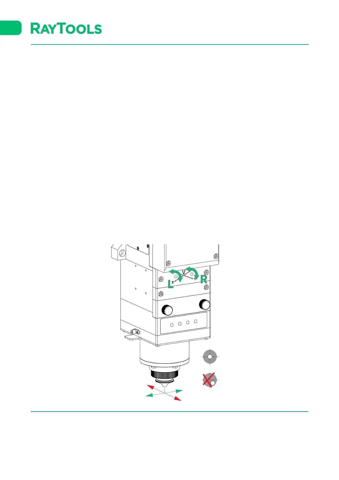
Lens alignment of laser cutting head can be finished by adjusting focus lens, X-Y direction. The X/Y adjusting knob is
located above bottom cover glass as shown below. Adjusting the 2 knobs until the beam is located in the middle of
nozzle. Make sure the laser beam output from the center of nozzle. A method commonly used is tape dotting method
as below:
▪ Fix the cutting head with a big size nozzle (tip size shall be larger than beam size) or adjust to nearly zero focus.
▪ Pick a scotch tape, flatten it and stick it to the nozzle tip.
▪ Open the red light of the laser. Find and observe the position of red light in the scotch tape.
▪ Shoot laser at low power to check beam penetration size. Beam penetration shall be circle and located in the
nozzle tip center.
▪ Adjust the 2 X/Y adjusting knobs to get beam aligned. The max X/Y adjusting range is roughly from -1.5mm to
+1.5mm.
▪ Tear off the tape and check the shooting hole position in tape.
▪ Repeat the above steps to find out relatively centered position.
Figure 4.1— Beam Adjustment
 Loading...