INPUT
/OUTPUT
CHANNEL
REGISTERS
Channel
Address
Register
lCAR)
Channel
Command
Register-II
lCCR-1n
Input/Output
Operation
•
The
Channel Address Word
(CAW),
Channel Block
Address
(CBA),
and
the
Channel Command
Word(s)
(CCW)
are
stored
by
the
program
in
main
memory. However, when
an
input/output
operation
is initiated,
the
information
contained
in
the
CAW, CBA,
and
the
first CCW is
trans-
ferred
to
the
scratch-pad
input/output
channel
registers
for
the
channel
specified
by
the
Start
Device instruction. (See table 11.) Because
the
access
speed
in
scratch-pad memory is
faster
than
main
memory,
faster
servicing
of
input/output
devices is possible. These
registers
also eliminate
the
need
for
the
program
to -reset channel command words, because
incrementing
and
decrementing addresses
and
byte count is done
in
scratch-pad
memory.
These
registers
allow the
input/output
operation to proceed
under
control
of
the
specified channel,
thereby
permitting
normal
mode processing
to continue.
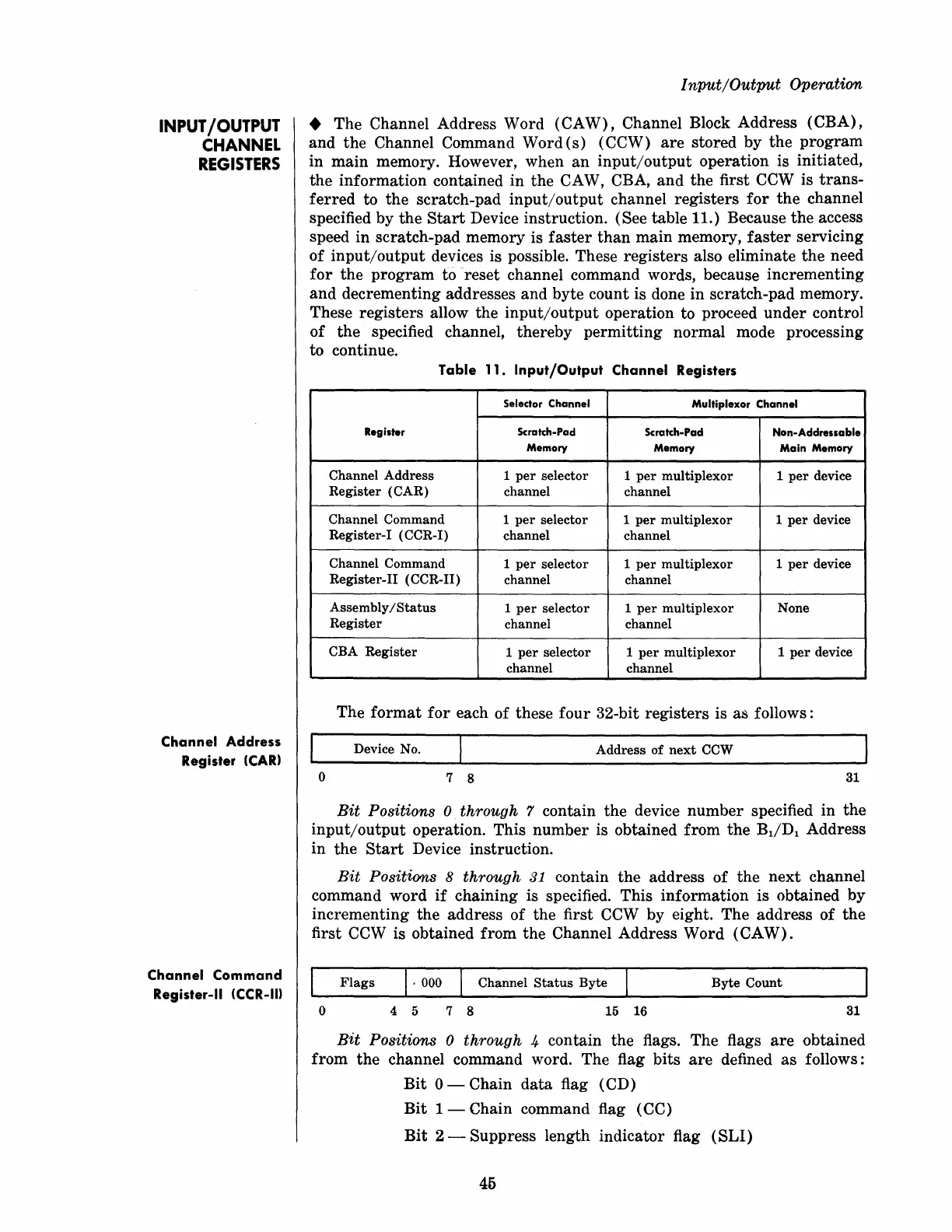
Table
11.
Input/Output
Channel
Registers
Selector Channel
Multiplexor Channel
Register
Scratch-Pad
Scratch-Pad
Non-Addressable
Memory
Memory Main Memory
Channel
Address
1
per
selector
1
per
multiplexor
1
per
device
Register
(CAR)
channel
channel
Channel
Command
1
per
selector
1
per
multiplexor
1
per
device
Register-I
(CCR-I)
channel channel
Channel
Command
1
per
selector
1
per
multiplexor
1
per
device
Register-II
(CCR-II)
channel channel
Assembly/Status
1
per
selector
1
per
mUltiplexor
None
Register
channel
channel
CBA
Register
1
per
selector
1
per
multiplexor
1
per
device
channel
channel
The
format
for
each
of
these
four
32-bit
registers
is
as
follows:
Device No.
Address
of
next
CCW
o
7 8
31
Bit
Positions 0 through 7 contain
the
device
number
specified
in
the
input/output
operation. This
number
is obtained
from
the
BdDl
Address
in
the
Start
Device instruction.
Bit
Positions 8 through 31 contain
the
address
of
the
next
channel
command
word
if
chaining
is specified.
This
information
is obtained
by
incrementing
the
address
of
the first CCW by eight.
The
address
of
the
first CCW is obtained
from
the
Channel Address
Word
(CAW).
Flags
I·
000 I
Channel
Status
Byte
Byte
Count
o 4 5 7 8
15
16
31
Bit
Positions 0 through 4 contain
the
flags.
The
flags
are
obtained
from
the
channel command word. The flag
bits
are
defined
as
follows:
Bit
0 - Chain
data
flag (CD)
Bit
1 - Chain command flag ( CC)
Bit
2 -
Suppress
length
indicator
flag
(SLI)
45