2 -
LM800/ 8000
COMMON CALIBRATION
11
2.3 Calibration Factors
The previous pages cover "Sensor Setup" and "Auto Cal" on the "Calibration" menu. With the exception of "6.
Surge Factors" , the menu items,
2. Static Factors
3. Dynamic Factors
4. Dyn. Comp. Factors
5. Stat. Comp. Factors
6. Surge Factors
7. Angle Factors
simply display the factors resulting from the Auto Cal routine for the
attachment selected. Also, Speed compensation/Static Compensation
can be switched on or off.
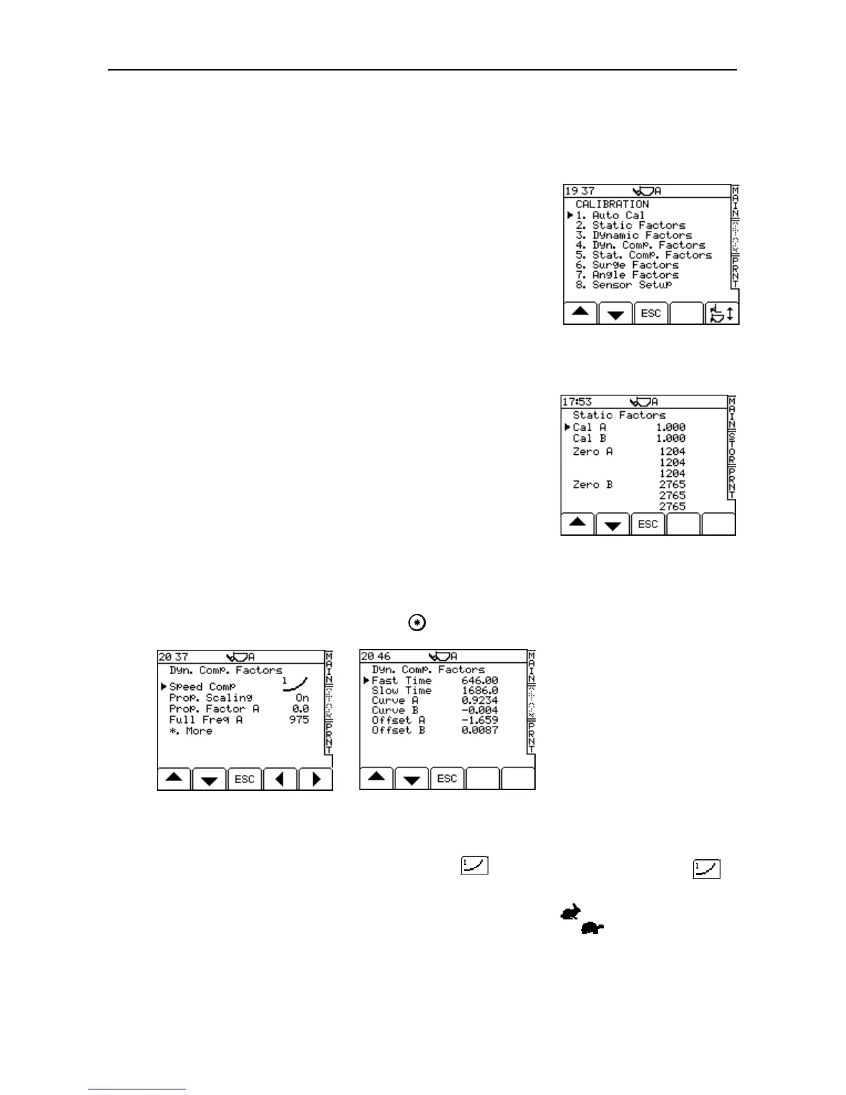
2.3.1 Displaying Static/Dynamic Factors
These are the factors resulting from the AUTOCAL routine. From the
"Calibration " menu, select "2. Static Factors” or "3. Dynamic Factors" to
display them (fig. 17a). The Zero factors are also stored here. The first
Zero factor (for both A and B sensors) refers to the initial Autocal Zero
which is carried out on initial verification. The second Zero factors is the
frequency stored at the initial switch on bucket Zero. The third Zero
factor is the frequencies stored during any other Zero routine. These are
used to perform the Zero Setting Checks.
2.3.2 Dynamic Speed Compensation Factors (Dyn. Comp. Factors)
From the "Calibration" menu, select "4. Dyn. Comp Factors". There are two screens displaying various factors
that can be edited if required (17b, 17c). Press to advance to the second screen.
The first screen enables Dynamic Speed Compensation and Proportional Scaling to be switched on or off.
NOTE: There are two Speed compensation options: - "Type 1" and "Type 2". After performing the Auto Cal routine,
Speed Compensation is automatically set as "Type 1" ( ). For hydraulic systems, Type 1 ( )
should be set.
The second page shows the lift speed alarm limits in milliseconds. If the lift speed between the reference sensor
and the direction sensor is faster than the “Fast Time” (the smaller value), the symbol appears on the MAIN
screen. If the lift speed is slower than the “Slow Time” (the larger value), then the symbol is displayed.
“Curve A” and “Curve B” give the correction for the change in lift speed. If a fast lift gives a lower weight reading
than the slow lift, then the figure should be decreased, and always –ve e.g. changing –11.0 to –10.0.