3 – GENERAL SYSTEM SETTINGS
16
3 General System Settings
3.1 Output Port Setup
NOTE: Requires the Technician PIN number (default = 1234)
There are two 9-way ports on the back of the instrument.
Port 1 is the upper port.
Port 2 is the lower port.
From the SETUP menu, press,
NOTE: Port 1 and port 2 have an additional configuration for "Screen" output.
This option is not applicable in normal use.
The top port is factory set for connecting an RDS ICP printer, without further configuration being
necessary. If another printer is used (or you want to select an option other than a printer), you can
configure the settings from the ‘SETUP’ menu.
Port Output Mode Port function
‘Text’ Printer
’Data’ Direct cable link to PC
‘Card’ Top Port :- External Data Card Module
Bottom Port:- No external function – enables the internal SD Data Card Module
’Radio’ Telemetry via radio
’GSM’ Telemetry via mobile phone
‘Screen’ (For RDS use only)
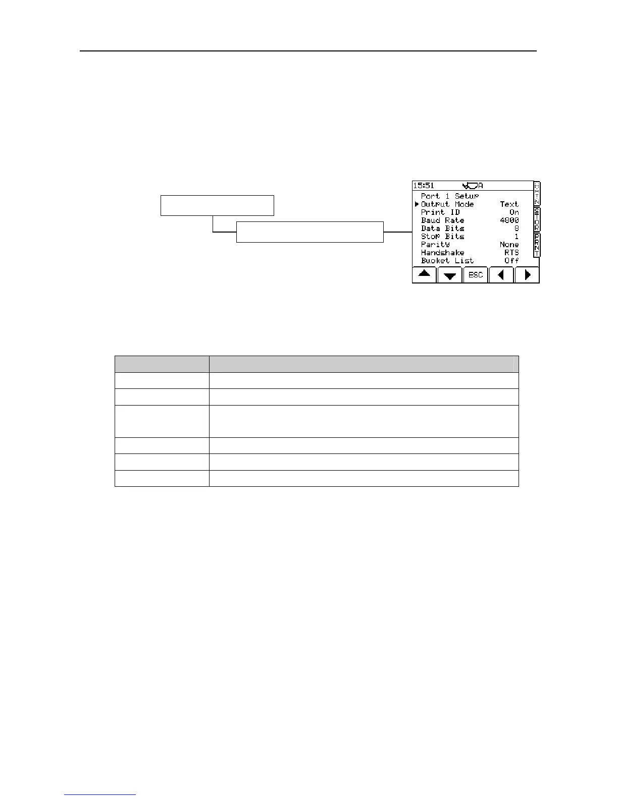
3.1.1 Set Output Mode
ASCII Text Output for Printers
Set the output mode to "Text". The data is output as ASCII text formatted to suit the RDS ICP 200 In-Cab
Printer.
The default settings (fig. 29) are for the RDS ICP 200 In-Cab Printer.
Print ID Off / On
Baud rate: 110 / 150 / 300 / 600 / 1200 / 2400 / 4800 / 9600 / 19,200 / 31,250 or 38,400.
Data Bits: 7 / 8
Stop Bits: 1 / 2
Parity: None / Odd / Even
Handshake: RTS / XON
Bucket List Off/On
NOTE 2: “Print ID” switches the “Instrument ID” function (ref. the Operation manual section 5.4) on or off. When
switched off the “Instrument ID” text (up to two lines each of twenty characters) will not appear on the printout.
NOTE 3: If you are using an existing printer from another manufacturer, it may operate with a different protocol. If it does
not work with the default settings, please refer to the printer instructions.
NOTE 4: “Bucket List” provides an itemised list of all bucket lifts on a ticket (only possible in “Customer” mode).
3. System Settings
Figure 29
1. Output Port Options (Enter PIN)