Installing ECUs Recon Blockage Plus™ Installation Manual
600840-000069, rev 1.0 Page 10 of 35
Installing the ECUs (Standard Orientation)
NOTE: This section is for installing the ECUs in the standard (vertical) orientation. If your dealer
ordered you a horizontal mounting kit, skip this section and use the instructions in Installing the
ECUs (horizontal installation).
Provided Parts
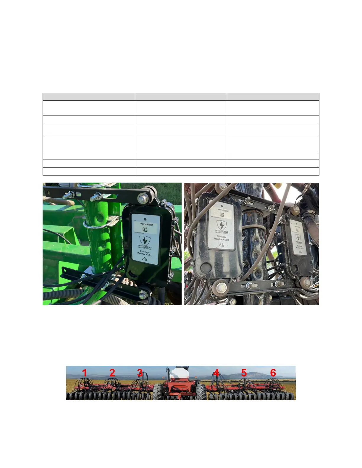
Figure 7: ECU installed on a tower (standard installation)
NOTE: ECUs can be mounted in any order; however, we recommend installing the ECUs in
numeric order from left to right (when facing the back of the tractor) based on the ECU’s serial
number. The serial number is located on the front of the ECU. Use the table in Appendix B to
record your system setup.
Figure 8: Installing the ECUs from left to right