Installing Flow Sensors Recon Blockage Plus™ Installation Manual
600840-000069, rev 1.0 Page 7 of 35
2. Installing Flow Sensors
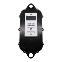
Flow sensors detect when product is flowing through the run.
Figure 1: Flow sensor
Provided Parts
Tools Needed
• 5/16 inch socket, 5/16 inch nut driver on a cordless drill, or a flathead screwdriver
• Measuring tape
• Cutting tool, such as a PEX tubing cutter, box cutter, or shears
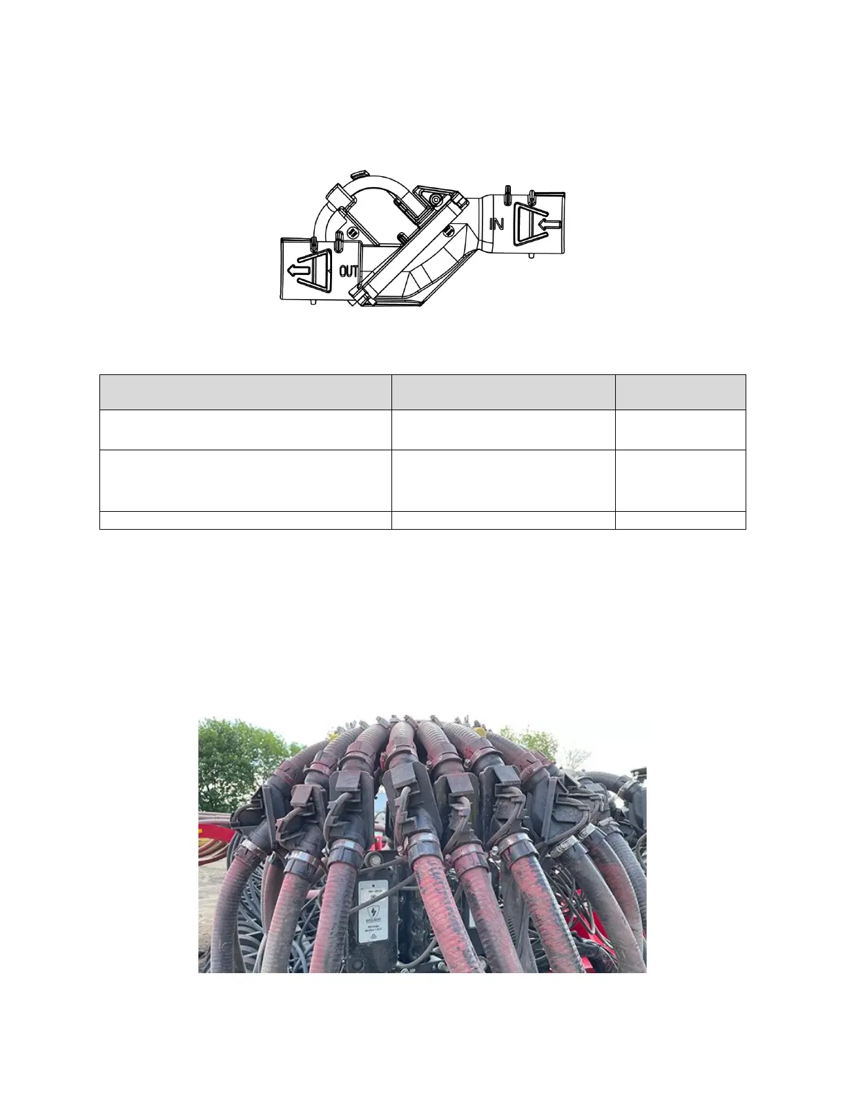
Installation Location
Installed at the beginning of every final run hose.
Figure 2: Flow sensor installation location