Installation Installing the Pump
13
A slight twisting of the UMP will loosen the seals and facilitate adjusting it to the correct
length. Do not rotate piping beyond 1/4 turn.
Figure 8. Loosening Locking Nut
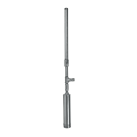
6. Referencing Figure 9, pull the UMP end until the distance between the bottom of the bulk head and the
bottom of the UMP is 3 inches (76 mm) shorter than the distance measured in Step 2.
Figure 9. Adjusting Pump Length
Take care not to damage the pigtail.
7. Tighten the column pipe locking nut and torque to 150 ft-lbs (203 N•m) minimum, then torque each set screw
in the locking nut to 10 ft-lbs. (14 N•m).
Set screw torque is critical to proper function.
8. Feed UMP cable through strain relief (supplied) and tighten cord grip to 3 ft-lbs (4 N•m) after removing excess
slack in the tank. Thread sealant is not required between cord grip and bushings. Threads are 1/2” NPT.
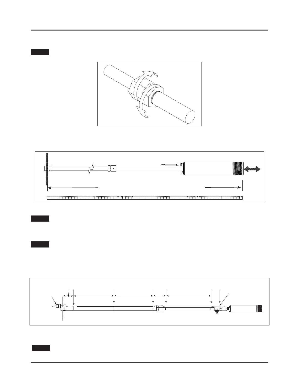
9. Secure the UMP cable to the column pipe with tie straps. Locate the tie straps approximately as shown in
Figure 10. Ensure the UMP cable is not in front of (blocking) the pressure relief nozzle (if applicable).
Figure 10. Tie Strap UMP Cable To Column Piping (Shown W/Fixed Pressure Relief Assembly)
10. Gently lower the assembly using manway cover.
Do NOT use the UMP cable as a lowering or restraining device as damage can occur.
1/4 turn maximum on piping
3'' (76mm) shorter than Step 2 measurement
1/2 Distance
Route cable on
opposite side of
pressure relief
No thread sealant
required for cord
grip and bushings
1/2 Distance
6" (151mm)