Installation Electrical Connections
16
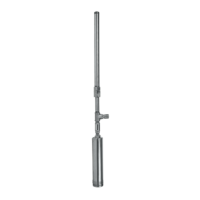
2. Remove the machined 1-1/8” hex cover from the end of the Adjustable Pressure Relief valve.
3. Adjust the set screw with the 1/4” hex key per Figure 13.
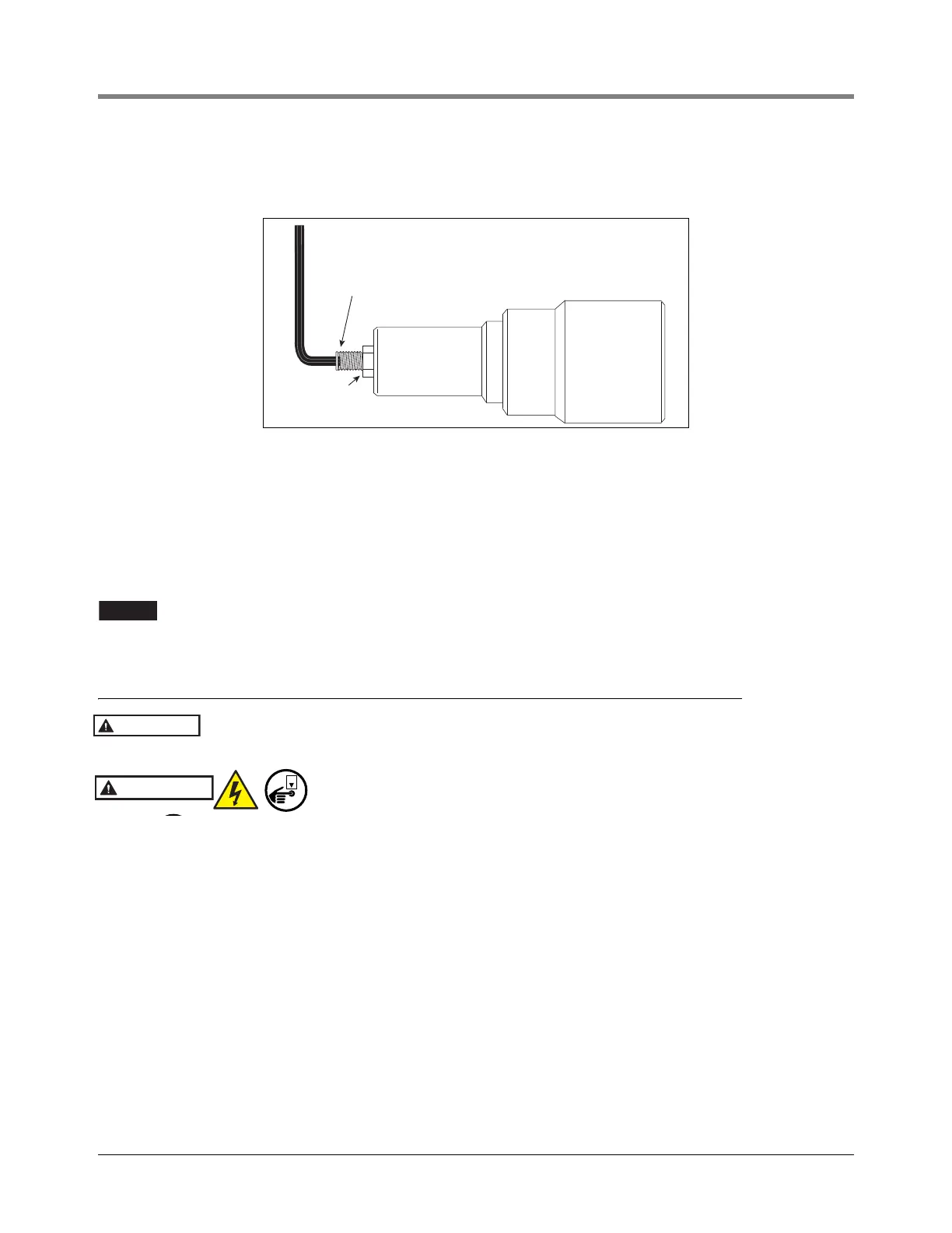
Figure 13. Setting Optional Adjustable Relief Valve Pressure
4. Turning screw clockwise increases pressure up to 50 psi (345 kPa) (maximum).
5. Determine desired flow through nozzles.
6. Adjust set screw to set flow through nozzles.
7. Lock down hex jam nut.
8. Replace hex cover and torque to 30 ft-lbs. (41 N•m).
Do not modify valve to allow for higher pressure! Failure to install the fixed pressure relief
valve or the adjustable pressure relief valve can lead to system overpressure and could
possibly damage the dispenser and DEF system.
Electrical Connections
The DEF pump is NOT designed for use in flammable liquids, or to be installed in
locations classified as hazardous per NFPA 70 (NEC)!
Disconnect, lock out, and tag power at the panel before servicing the
pump
.
In DEF fueling sites that are being upgraded to include a Control Box with capacitor, it is imperative to verify the
wiring connections between the pump and the Control Box. Energizing a pump with incorrect connections can
cause the thermal overload in the pump to trip open, resulting in a very lengthy wait for the thermal protector to
reset.
Resistance tests are always made with the power off and the wires disconnected from the Control Box.
Set up the electrical meter to the ohms (
) function. Measure the resistance between each pair of wires that run
out to the pump. Consider the three readings as “low”, “medium” and “high”. Ignore actual color of wires.
1. Locate the two wires that give the highest ohmmeter reading. Mark the remaining wire "BLACK".
2. Mark the wire "GREY" that in combination with the "BLACK" wire (as determined in Step 1.) gives the lowest
reading.
3. Mark the remaining wire "BROWN".
4. Connect the “GREY” wire to the “M1” terminal of the Control Box.
5. Connect the “BLACK” wire to the “M2” terminal of the Control Box.
6. Connect the “BROWN” wire to the “M3” terminal of the Control Box.
Insert hex key into indent of pressure adjustment
screw to set the relief pressure. Replace hex cover over
adjustment screw after setting desired pressure.
Jam nut
WARNING