Installation Wiring Diagrams
17
SIMPLIFIED WIRING DIAGRAMS
Wiring Diagrams
SINGLE TANK INSTALLATIONS
Figure 16 through Figure 25 contain example wiring diagrams for various single tank/submersible DEF pump
installations.
MANIFOLDED TANK INSTALLATIONS
When greater flow rates are needed, two pumps may be installed in the same piping system by means of a
manifold.Tandem systems offer backup support so operations can continue if one pump stops working.
Figure 26 through Figure 29 contain example wiring diagrams for various manifolded tanks/submersible DEF
pump installations featuring Isotrol Control Boxes.
ISOTROL CONTROL BOX WIRING PRECAUTIONS (Apply to Figure 22 through Figure 29):
The Isotrol Control Box is intended to provide electrical isolation between the dispens-
er pump enable (Hook) signal and the submersible turbine pump (STP) control relay.
Other energized sources of power can still exist within the dispenser even with this
device. The neutral connection to the N terminal of TB1 and N terminal of TB2 must be
from the service panel and be a permanently connected, unswitched connection.
• The N connection on TB1 and the eight N connections on TB2 may be spliced to a common neutral
wire from the service panel described above.
• Make only one ‘wire’ connection on each N terminal on TB2.
The phase of L1 (TB1) must match the phase of the power supplying the ATG device to
prevent cross phasing which may damage the input on some ATG equipment.
GENERAL WIRING PRECAUTIONS
• Wiring must be rated 90°C minimum.
• Make ground connection in accordance with local codes.
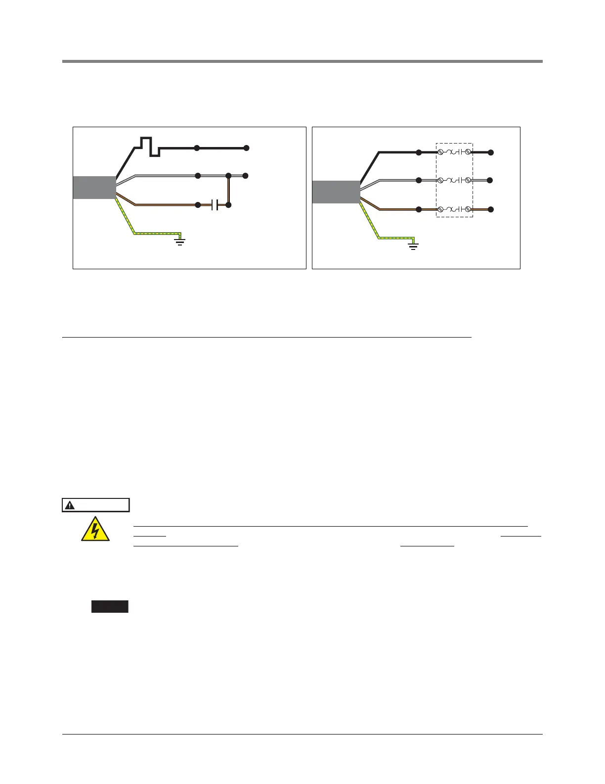
Figure 14. Single Phase Wiring Diagram Figure 15. Three Phase Wiring Diagram
Black
T
C
Grey
M2
M1
L2
L1
Brown
Yellow/Green
M3
M1 - Main
M2 - Common
M3 - Auxilliary
C - Capacitor
T - Thermal Device
Black
Grey
T3
T2
L3
L2
L1
Brown
Yellow/
Green
T1
Class 10
Starter With
Overloads