Installation Installing the Pump
15
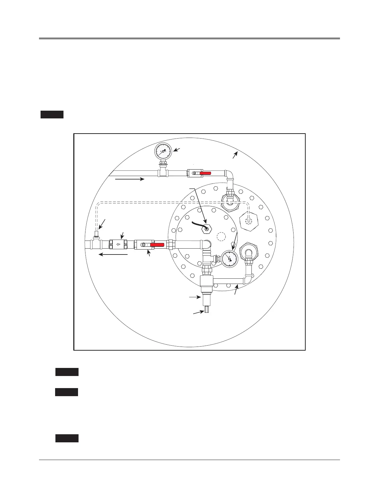
ADJUSTABLE PRESSURE RELIEF OPTION
If the fixed pressure relief kits are not ordered it is mandatory to install the adjustable pressure relief valve in the
sump. This valve is a 1” NPT fitting and will need to follow the same guidelines for material compatibility and
sealant. During installation, the technician will need to plumb this valve’s bypass back into the UST. A check valve
is recommended downstream of the optional adjustable pressure relief valve to maintain line pressure to
dispensers. See example installation in Figure 12.
To allow for thermal expansion, ensure line pressure relief is supplied/installed
downstream of the check valve.
Figure 12. Adjustable Pressure Relief Installation Example
When routing the return to the tank it may be required to extend the return line near
the bottom of the tank to avoid any potential disruptions to the probe’s accuracy.
Return flow from adjustable relief valve should be separate from recirculation loop if
present.
The adjustable pressure relief valve can be used in conjunction with the optional pressure gage to set to system
pressure.
1. Install optional pressure gage if desired.
Carefully apply sealant to port to avoid contamination of gauge.
10 50
20
60
30
40
Ball valve
(Typ.)
DEF discharge
line to dispensers
Optional
Recirculation Loop
Thermal relief
UMP cable
strain relief
Adjustable
pressure relief
valve
Return ow piping
(back to tank)
Pressure
gauge (Typ.)
Sump
Check valve
Machined
hex cover
10 50
20
60
30
40