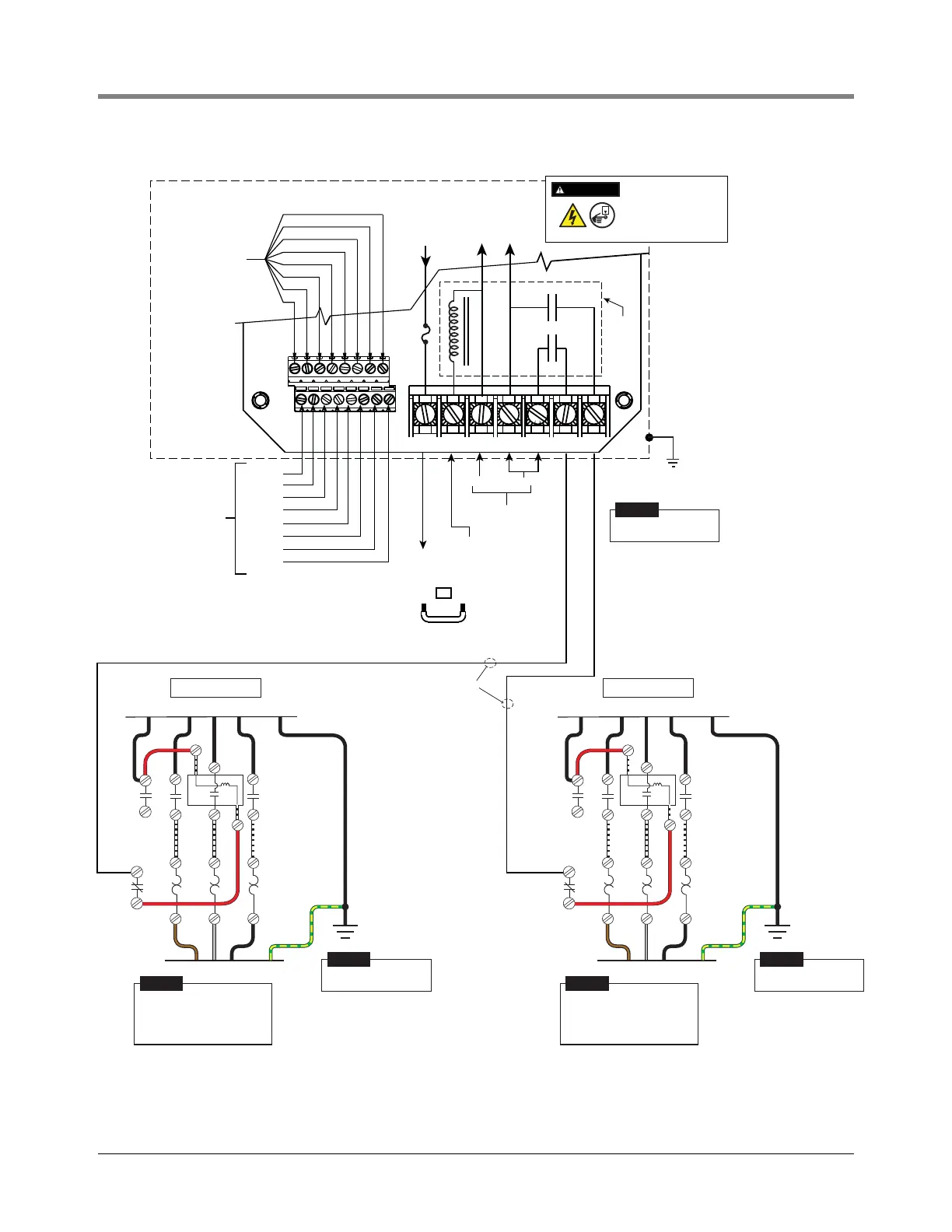
Figure 29. Isotrol W/Relay To Manifolded 208/240 Vac Remote Control Boxes (Starters) W/120 Vac Coil And
NEUTRAL
DISPENSER INPUTS
HOT
TB2
TB1
ATG S NL1L2M2M1
123 45678
CHANNEL 1
CHANNEL 2
CHANNEL 3
CHANNEL 4
CHANNEL 5
CHANNEL 6
CHANNEL 7
CHANNEL 8
L1N
UNSWITCHED
NEUTRAL TO TB2
ISOTROL CONTROL BOX (P/N 880-047-1)
120 VOLT
DISPENSER
SIGNALS
120 VOLTS FROM
SUPPLY PANEL
OUTPUT
120V
TO ATG
COIL
TERMINAL
120V
FROM ATG
RELAY
TO CIRCUIT
OUTPUT FROM
CIRCUIT
1A
OR
PHASE ON L1 MUST BE SAME AS DEVICE
CONNECTED TO ATG TERMINAL
JUMPER TO CONTROL RELAY
ON BOARD DIRECTLY
Grey
Black
Brown
T1
L1
L1 L2NL3
L2
L3
T2 T3
To 208/240 V Supply
120 V Coil
3 Ambient
Compensated
Heaters
COIL
2
9
3
To UMP
Grey
Black
Brown
T1
L1
L1 L2NL3
L2
L3
T2 T3
To 208/240 V Supply
120 V Coil
3 Ambient
Compensated
Heaters
COIL
2
9
3
To UMP
120 VOLT TO CONTROL BOX
DISCONNECT, LOCK OUT,
AND TAG POWER AT THE
POWER PANEL BEFORE
WIRING THE PUMP.
WARNING
OFF
Make ground connection in
accordance with local codes.
NOTICE
Make ground connection in
accordance with local codes.
NOTICE
Make ground connection in
accordance with local codes.
NOTICE
Connect To
Electrical Ground
Connect To
Electrical Ground
Connect To
Electrical Ground
Starter is wired for 208/240 V
to pump motor, 120 V from
Isotrol or dispenser switch.
Remove red wire connecting
9 to L2.
NOTICE
Starter is wired for 208/240 V
to pump motor, 120 V from
Isotrol or dispenser switch.
Remove red wire connecting
9 to L2.
NOTICE