Output Modules
The main control, optional Alarm, optional Cooling output and optional
Valve Position control output sockets must be fitted with the appropriate
output module. Output modules are shipped separately and must be installed
by the user.
Output Module Restrictions
With somemodels,the Alarmoutputs andValve Positionoutputs sharethe
same common terminal. When using these models, the same type of output
modules are usually installed in these positions.
Installing Output Modules
To install an output module into the controller, removethe b ezel assembly
from the case (See Removing Bezel Assembly, page 5). Locate the correct
output module socket (OP1, AL1, or AL2/OP2, see Figure 6, Hardware, or
label outside of case) and plug the output module into the socket. No
re-programming is required. If changing an output module type, be sure the
appropriate output interface wiring changes are made. Re-install the bezel
assembly when complete.
Note: For Valve Positioner models, the circuit board markings have the
following meaning:
AL1 - Open Output
AL2/OP2 - Close Output
OP1 - Alarm #1 Output
OUTPUT MODULE “OUTPUT ON” STATE
Relay Normally open contact is closed.
Logic/SSR Drive Source is active.
Triac Solid state switch is closed.
Typical Connections
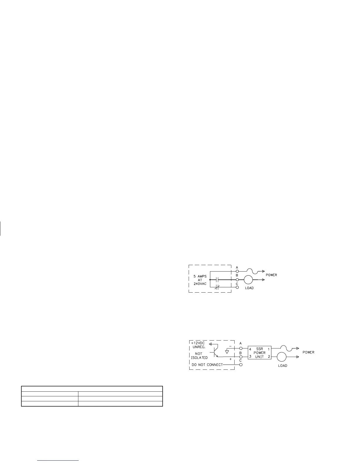
Relay:
Type: Form-C
Rating: 5 Amps @ 120/240 VAC or 28 VDC (resistive load), 1/8 HP @
120 VAC (inductive load).
Life Expectancy: 100,000 cycles at maximum load rating. (Decreasing
load and/or increasing cycle time, increases life expectancy).
Logic/SSR Drive:
Type: Non-isolated switched DC, 1 2 VDC typical
Drive: 45 mA Max. Can drive multiple SSR Power Units.
Figure 3, Relay Module
Figure 4, Logic/SSR Drive Module
 Loading...