Signal Wiring
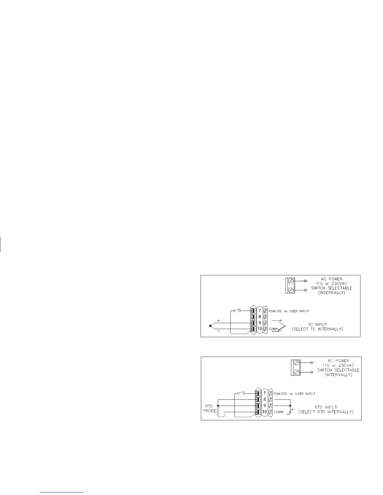
When connecting the thermocouple or RTD leads, be certain that the
connections are clean and tight, refer to Figures 7 and 8 for terminal
connections. If the thermocouple probe cannot be connected directly to the
controller,thermocouple wireor thermocouple extension-grade wiremustbe
used to extend the connection points (copper wire does not work). Always
refer to the thermocouple manufacturer’s recommendations for mounting,
temperature range, shielding, etc. For multi-probe temperature averaging
applications, two or more thermocouple probes may be connected to the
controller (always use the same type). Paralleling a single thermocouple to
more than one controller is not recommended. Generally, the red wire from
the thermocouple is negative and connected to the controller’s common.
RTD sensors are used where a higher degree of accuracy and stability is
required than is obtained with thermocouples. Most RTD sensors available
are the three wire type. The third wire is a sense lead for canceling the effects
of lead resistance of the probe. Four wire RTD elements may be used by
leaving one of the sense leads disconnected. Two wire RTD sensors connect
between terminals # 8 and #10. A sense wire connected to terminal #9, is
requiredforoperation.The sensewirecanbeconnected ineitheroftwo ways:
A) Install a copper sense wire of the same wire gauge as the RTD leads.
Connect oneend ofthe sensewire atterminal#9, and connectthe otherend
ofthe sensewireattheprobe(o nthe terminal#8side). Completelead wire
compensation is obtained. This is the preferred method.
B) Connecta shortingwire directly fromterminal #9to terminal#8, as shown
in Figure 8, RTD Connection. A temperature offset error of 2.5°C/ohm of
leadresistanceexists. Theerrormaybecompensatedforby programminga
temperature offset.
Note: With extended cable runs, be sure the lead resistance is less than 10
ohms/lead.
Figure 7, Thermocouple Connection
Figure 8, RTD Connection
 Loading...