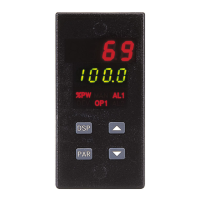
Output Module (2-OP)
The controller has parameters that affect how the main control output
(OP1) responds to temperature changes and sensor failures.
Time Proportioning Cycle Time (CYCt)
Theselectionof cycletime dependson thetime constantof theprocess and
the type of output module used.
CYCt - 0 to 250 seconds
For best control, a cycle time equal to 1/10 of the process time constant, or
less is recommended; longer cycle times could degrade temperature control,
and shorter cycle times provides little benefit at the expense of shortened
relay life. When using a Triac module or a Logic/SSR drive output module
with the SSR Power Unit, a relatively short cycle time may be selected.
A setting of zero keeps the main control output and front panel indicator
off. Therefore, if using the analog output for control, the main output and
indicator can be disabled. This parameter is skipped for Valve Positioner
models.
Output Control Action (OPAC)
For heat and cool applications, the main output (OP1) is normally used for
heating (reverse acting) and the optional cooling output (OP2) is normally
used for cooling (direct acting).
OPAC - rEv (Reverse acting)
drct (Direct acting)
If drct(direct acting) isselected, the main output(OP1) is directacting and
the cooling output (OP2) is reverse acting.
Note: When using a relay output module, th e control action may also be reversed
by using the normally closed contacts.
The linear DC analog output, when assigned to output power (OP) for
control purposes, tracks the controller output power demand. A direct acting
linear output signal can be implemented in two ways:
1. Use “ direct” for output control action (OPAC).
2. Interchange the two analog output scaling points ANLO & ANHI (see
Linear DC Analog Output, page 27).
Output Power Limits (OPLO & OPHI)
Enter the safe output power limits for the process. These parameters may
also be used to limit the minimum and maximum controller power due to
process d isturbances or setpoint changes, to reduce overshoots by limiting
the process approach level.
OPLO & OPHI - 0 to 100%
If the cooling option is installed, the limits range from:
OPLO & OPHI - -100 to 100%
With the cooling option installed, the Lower Limit can be set to less than
0% to limit maximum cooling or set to greater than 0% to limit minimum
heating. Set the High Limit to less than 0% to limit minimum cooling or
greater than 0% to limit maximum heating. When controlling power in the
manual mode, the output power limits do not take effect.
Sensor Fail Preset Power (OPFL)
If afailed sensor is detected,the control output(s)default to ap reset power
output.
OPFL - 0% (OP1 output full “off”) to 100% (OP1 output full “on”)
If the cooling option is installed, the range is extended from:
OPFL - -100% to +100%
At 0%both outputsare off,at 100%OP1 is onand OP2is off, andat -100%
OP2 is on and OP1 is off. The alarm outputs always have an up-scale drive
(+9999), independent of this setting, for failed sensor.
For position mode valve controllers, the valve is positioned according to
the setting of this parameter.
For velocity mode valve controllers, the following actions occur:
Velocity mode: OPFL = 0%, valve CLOSE output activates
OPFL = 100%, valve OPEN output activates
OPFL = any other setting, both valve outputs disable

 Loading...