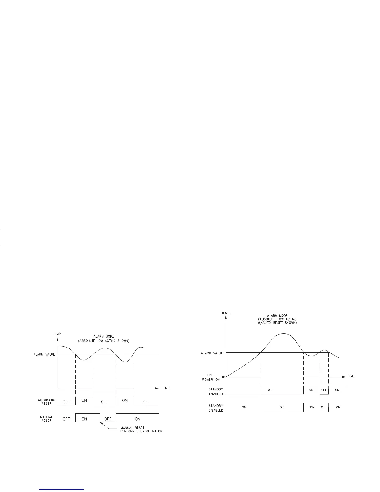
Alarm Reset (rSt1, rSt2)
Each alarm reset action may be independently conf igured.
LAtC - Latching
Auto - Automatic
Latched alarms require operator acknowledgment to reset the alarm
condition. The front panel buttons can be used to reset an alarm when the
controller is in the hidden mode (see Hidden Function Mode,page21).An
Alarmconditionmayalsobe resetviathe RS485serialinterface orbytheuser
input. Automatic (Auto) reset alarms are reset by the controller when the
alarm condition clears. Figure 16, Alarm Reset Sequence, depicts the reset
types.
Alarm Standby Delay (Stb1, Stb2)
The alarm(s) may be independently configured to exhibit a power-on,
standby delaywhich suppressesthe alarmoutput fromturning “ON”until the
temperature f irst stabilizes outside the alarm region. After this condition is
satisfied,the alarmstandbydelayis canceledand thealarmtriggersnormally,
untilthenext controllerpower-on.Figure17,AlarmStandbyDelaySequence
depicts a typical operation sequence.
Alarm Value (AL-1, AL-2)
The alarm values are either absolute (absolute alarms) or relative to the
setpoint value (deviation and band alarms). An absolute alarm value is the
value that is entered. A relative alarm value is offset from the temperature
setpoint value by the amount entered and tracks the setpoint value as it is
changed.
AL-1 and AL-2 - -999 to 9999
If the alarmaction is set as a Band Alarm, then only a positivevalue can be
entered.
AL-1 and AL-2 - 0 to 9999
Figure 16, Alarm Reset Sequence
Figure 17, Alarm Standby Sequence
 Loading...