The alarm triggers under the two following conditions:
1. Thevalve slidewire feedbackposition does notmatch thecontroller output
power (within the valve position deadband) after the valve fail time has
expired. The alarm indicates that the valve cannot be properly positioned
due to a malfunction of the valve or valve positioner.
2. The slidewire feedback signal is broken or out of range. In this case, the
valve position controller cannot position the valve.
Message display alarms “valv” and “slid” appear when conditions 1 and 2
occur, respectively, whether or not the alarm is configured as a valve fail
alarm. This alarm mode also applies to linear DC output used for valve
positioning. In this case, a slidewire signal must be supplied to the controller
for valve fail detection. To silence a triggered Valve Fail alarm, see Va lve
Fail Time Alarm (VFAL) parameter, page 39.
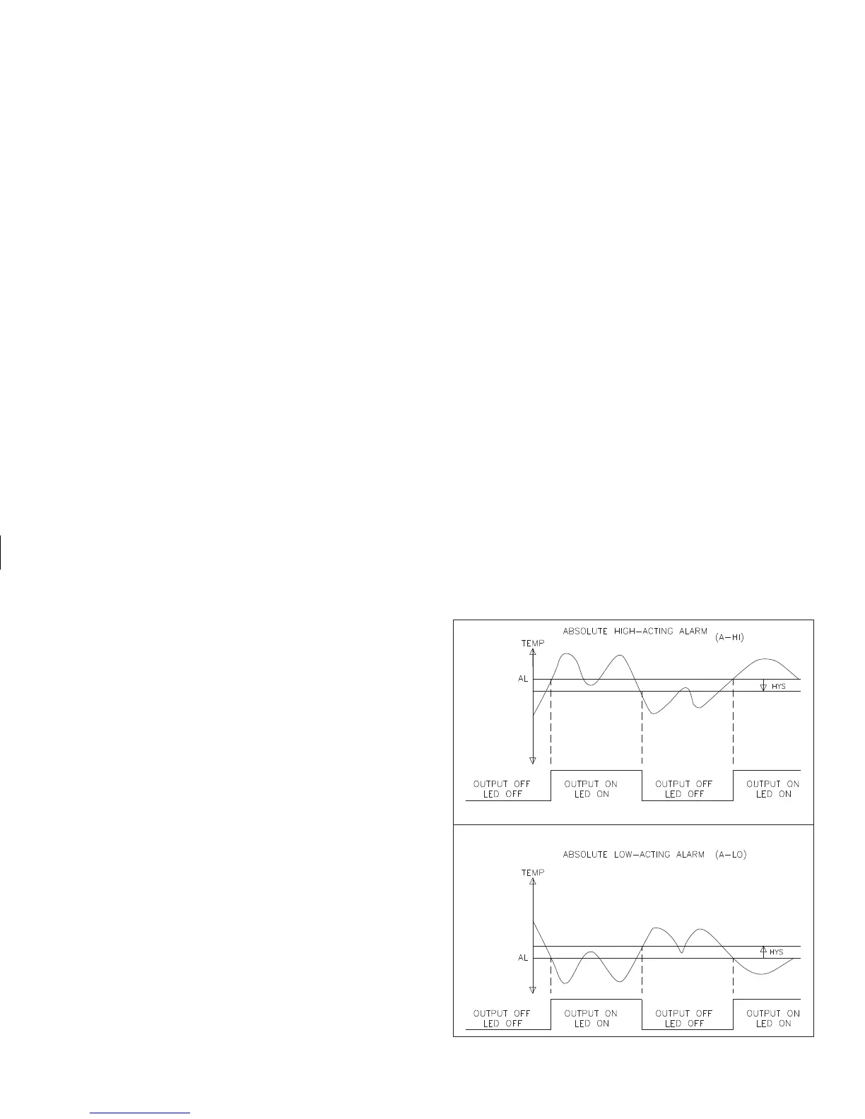
The alarm action figures describe the status of the alarm output and the
front panel indicator for various over/under temperature conditions. (See
Output Module “OUTPUT ON” State Table, page 6, for definitions, under
installing output modules section.) The alarm output wave form is shown
with the output in the automatic reset mode.
Note: Select the alarm action with care. In some configurations, the front panel
indicator (LED) might be “OFF” while the output is “ON”.
 Loading...