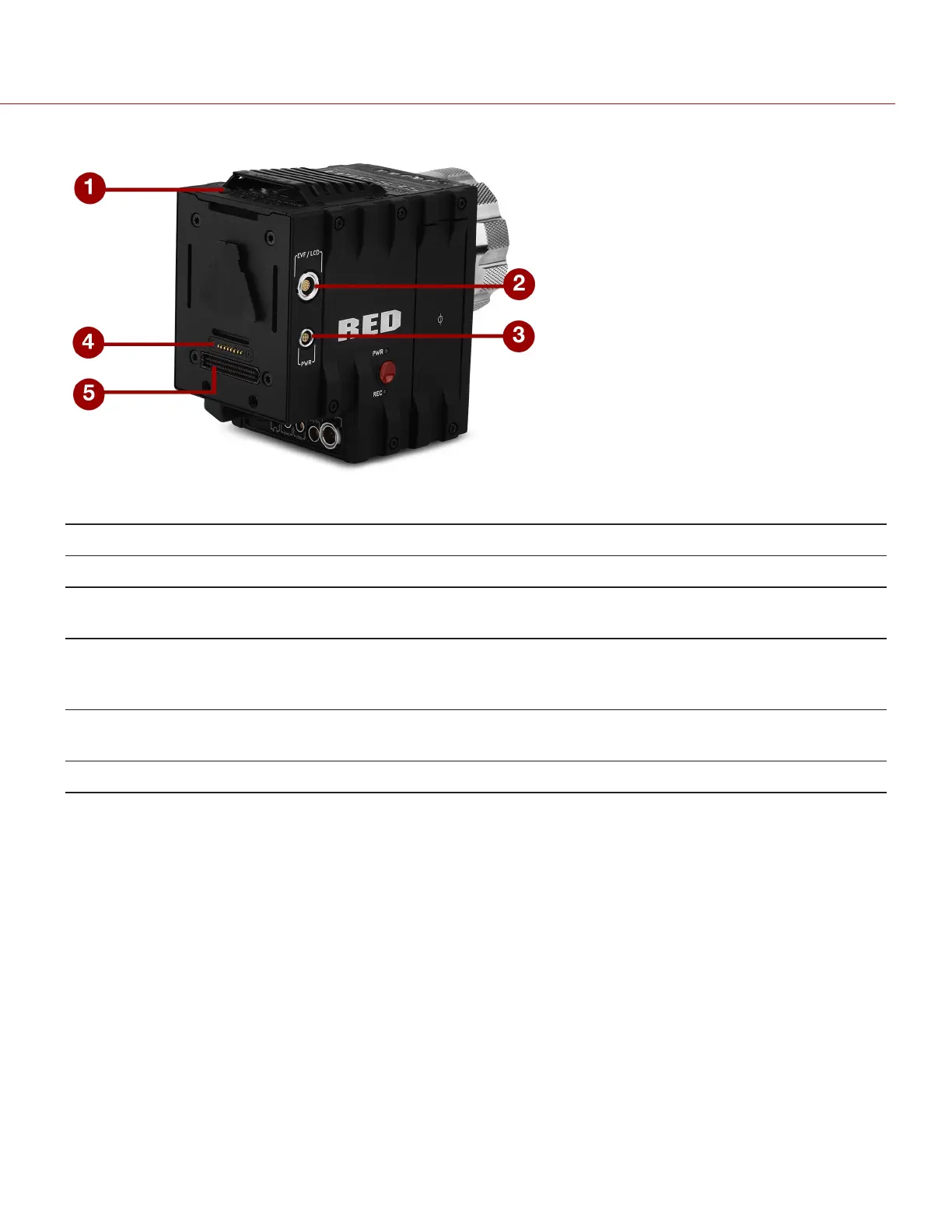
+1 ADAPTOR MODULE CONNECTIONS
Figure: +1 Adaptor Module
# CONNECTOR CONNECTOR TYPE CONNECTORFUNCTION
1 Mounting 1/4-20 mounting Supports bolt-on auxiliary equipment
2 EVF/LCD
1
N/A Custom digital video and power interconnection between the
camera and RED EVF or LCD; Pinout not published
3 Auxiliary power
out (PWR)
4-pin 0B LEMO Supplies unregulated (+) 11.5 to 17 VDC battery pass-through;
Connect to 2-pin LEMO accessories with RED 4-Pin to 2-Pin
Adaptor Cable; Max sustained current is 2 A
4 REDMOTE
®
dock
connector
8-point POGO
connector
Power and support for the REDMOTE
5 Dock connector SEARAY connector Supports power and communication with modules
1. DO NOT use the EVF/LCD port on the +1 Adaptor Module if a Pro I/O Module is connected to the DSMC BRAIN. The Pro I/O Module overrides
the EVF/LCD and AUX power out ports when connected.
NOTE: The default auxiliary power output setting is on. Use the on-screen menu to toggle this setting ON/OFF. In the
menu screen, go to: Power > Power Out > +1 PWR. After a camera firmware upgrade or factory reset, the default
auxiliary power output setting is turned on. Thereafter, the last power output setting is restored.
C OPYRI G HT © 2017 RED.C OM , LLC 955- 0038, REV-AD| 27
RED DSMC POWER OPERATION GUIDE