P36E-4 Zero Clearance Direct Vent Gas Fireplace
50
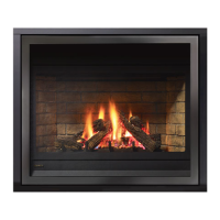
NOTE: Wiring schematics for P36E-4 (120 Volts),
plug-in fan circuit with speed control switch on wall.
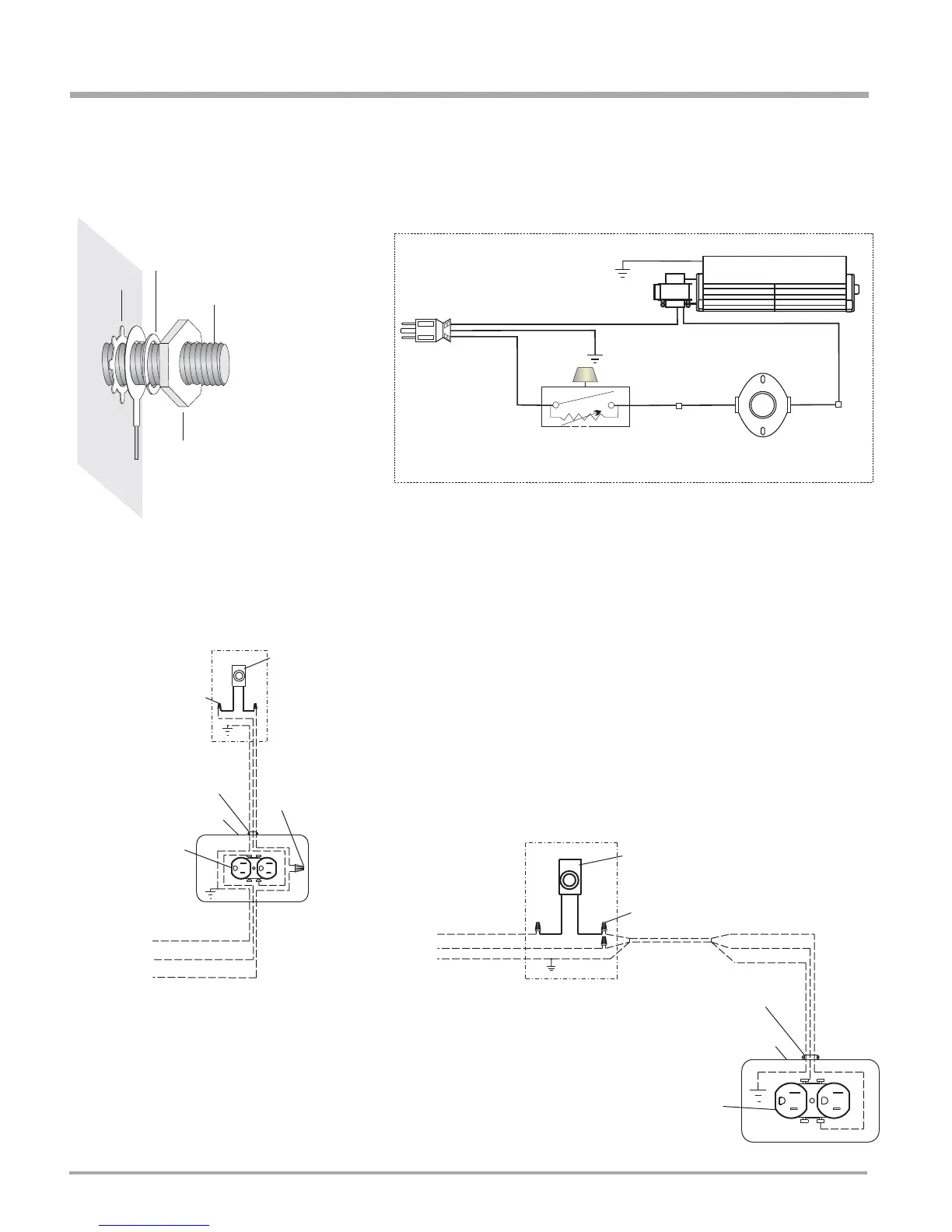
Lockwasher
Fan
ground wire
Nut
#8 Ground Lug
(for mobile home)
Star washer
Ground
Green
Neutral
Live
Black Red Red
Fan Thermodisc
(normally open)
Ground
ON OFF
Rotary Speed
Control
120V AC
60 Hz
Fan
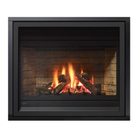
P36 E lectrical Connection Alternative Scheme "A",
Power at Stove
Wall Junction Box
*Speed Control
Switch with
lead wires
(Regency)
Wire Nuts
Wire Nuts
14 AWG wire
14 AWG wire
*Wire C la mp
*Receptacle Box
ins ide stove
*Receptacle
(dedicated use
by stove fan only)
120 Volts
60 Hz
C opper Ground
White (Neutral)
Black (Hot)
~
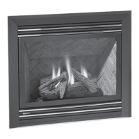
P36 E lectrical Connection Alternative Scheme "B",
Power at Switch
Wall Junction Box
*Speed Control
Switch with lead wires
Wire Nuts
14 AWG wire
*Wire C lamp
120 Volts
60 Hz
C opper G round
White (Neutral)
Black (Hot)
Wire
Black
White
G round
*Receptacle Box
ins ide stove
~~
*Receptacle
(dedicated use
by stove fan only)
* = s upplied with fan kit
Other parts are to be s upplied
by electrician or ins taller
OPTIONAL FAN WIRING DIAGRAM
INSTALLATION