Renesas Starter Kit+ for RZ/T2M 6. Configuration
R20UT4939EG0100 Rev. 1.00 Page 47 of 87
Apr 20, 2022
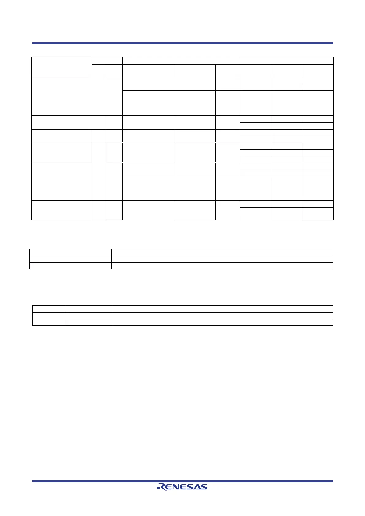
Table 6-25: External BUS & SDRAM Configuration Option Links (4)
Signal name
Pin
Signal Fit DNF
Fit DNF
BSC_CAS#_M E3 P01_0
BSC_CAS#
-
ETH2_MDIO
(SW6-1 = ON),
CN19
IC16.50 - -
BSC_WR#_M K5 P03_4 BSC_WR#
-
BSC_DQMLU_M B4 P23_2 BSC_DQMLU
-
BSC_DQMLL_M E6 P23_1 BSC_DQMLL_WE0#
IC12.22
(SW6-1 = ON)
-
BSC_CKE_M H6 P01_1
BSC_CKE
-
ETH2_MDC
(SW6-1 = OFF),
CN18
- IC16.48 - -
BSC_CKIO_M M1 P04_1 BSC_CKIO
(SW6-1 = ON)
-
JA3-A.44 - -
Table 6-26 below details the function of the switches associated with the SDRAM.
Table 6-26: External BUS & SDRAM Configuration Switch Settings
Enable the external bus signal.*
1
Enables signals other than the external bus. (CAN, Emulator, I
2
C, etc.)
*
1
: SDRAM and Ethernet / Switch / EtherCAT port 2 cannot be used at the same time.
Table 6-27 below details the function of the jumpers associated with the SDRAM.
Table 6-27: External BUS & SDRAM Configuration Jumper Settings
CN17
Connect 3.3V Power rail to VCC1833_2. (When using SDRAM)
*1
Connect 1.8V Power rail to VCC1833_2. (When using Ethernet port 2)
*1
: When using SDRAM, use the Ethernet switch (CN18-CN20) setting at 2-3.
 Loading...


