TPS-1 User’s Manual: Hardware 2. Pin function
R19UH0081ED0107 Rev. 1.07 page 16 of 86
Jul 30, 2018
2.4. Signals for IRT Communication
The TPS-1 synchronizes the IO device to the PROFINET controller and generates trigger signals that are used for application synchronization.
T_IO_Input relates peripheral inputs and T_IO_Output relates peripheral outputs to the data cycle.
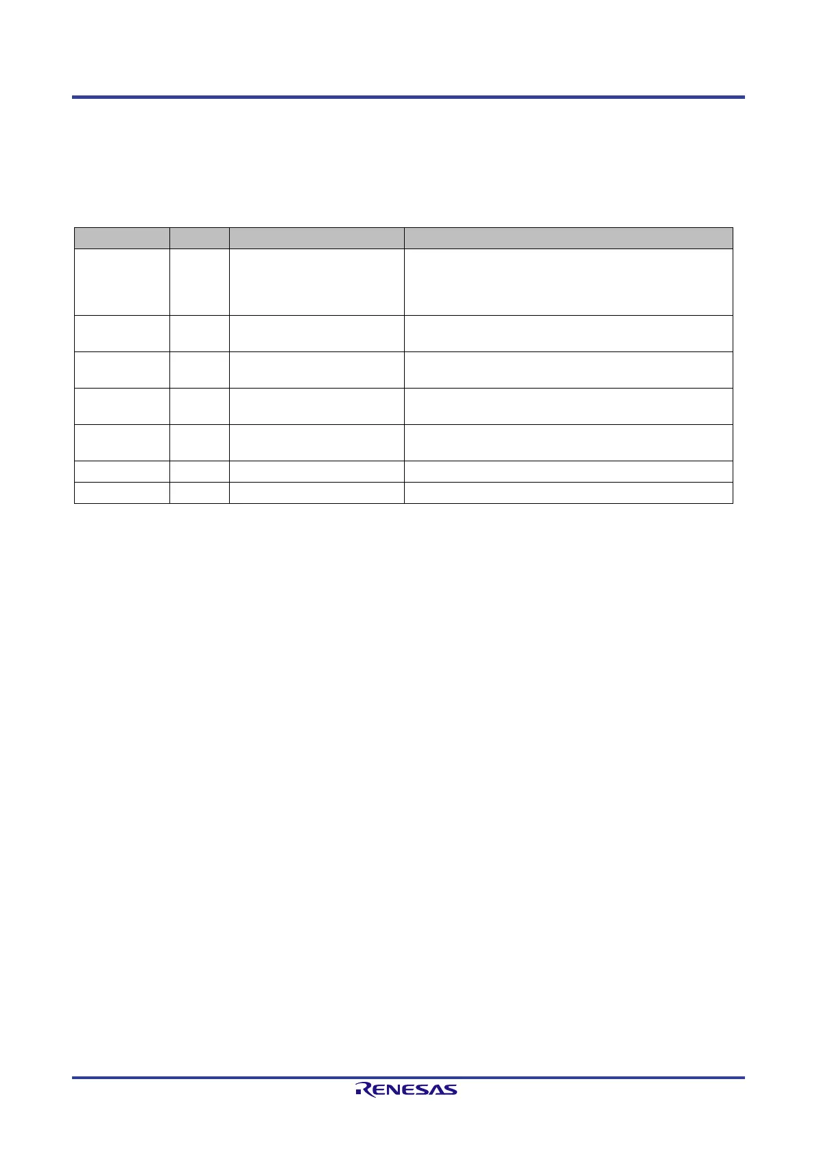
Table 2-4: IRT Communication Signals
Signal Pin Function Comment
TEST_SYNC N12 Start of bus cycle A signal on this pin signalizes a new cycle event. It is
used as well to test the synchronization during the
certification. The signal should be made accessible for
measurement purposes.
Time at which the input data must be read from
process.
T2 H11 To (T_IO_Output) Data can be used by the application at this configured
time.
T3 G11 T_IO_InputValid Time at which the input data must be in the transfer
buffer.
This signal indicates when the data for output are
available.
T5 E11 -for further use
 Loading...