TPS-1 User’s Manual: Hardware 4. Shared memory structure
R19UH0081ED0107 Rev. 1.07 page 34 of 86
Jul 30, 2018
4. Shared memory structure
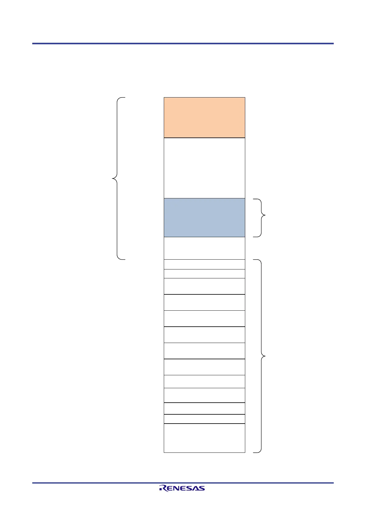
Figure 4-1 describes the structure of the shared memory. The serial and parallel interfaces see the same memory image (64 Kbyte). If you use 4 kByte
memory pages then you can only use the NRT Area up to 0x9FFF.
0x0000
0x2000
0x2800
0x8000
reserved
reserved
Output Area
Input Area
MC Provider
Area
(2k Byte)
TPS-1 Information Area
Device Vendor Information
RecordMailbox
Supervisor AR
0xFFFF
IO RAM
NRT
Area
(32k Byte)
Event and IO
area
(32k Byte)
Slot/Subslot configuration
reserved
TCP/IP Mailbox
AR0
RecordMailbox
AR0
AlarmMailbox high
AR0
AlarmMailbox low
AR1
RecordMailbox
AR1
AlarmMailbox high
AR1
AlarmMailbox low
RecordMailBox
Implicit AR
Event-Unit
Figure 4-1: TPS-1 Shared Memory Structure (Dual Ported RAM)
 Loading...