TPS-1 User’s Manual: Hardware Appendix. B Board Design Information
R19UH0081ED0107 Rev. 1.07 page 85 of 86
Jul 30, 2018
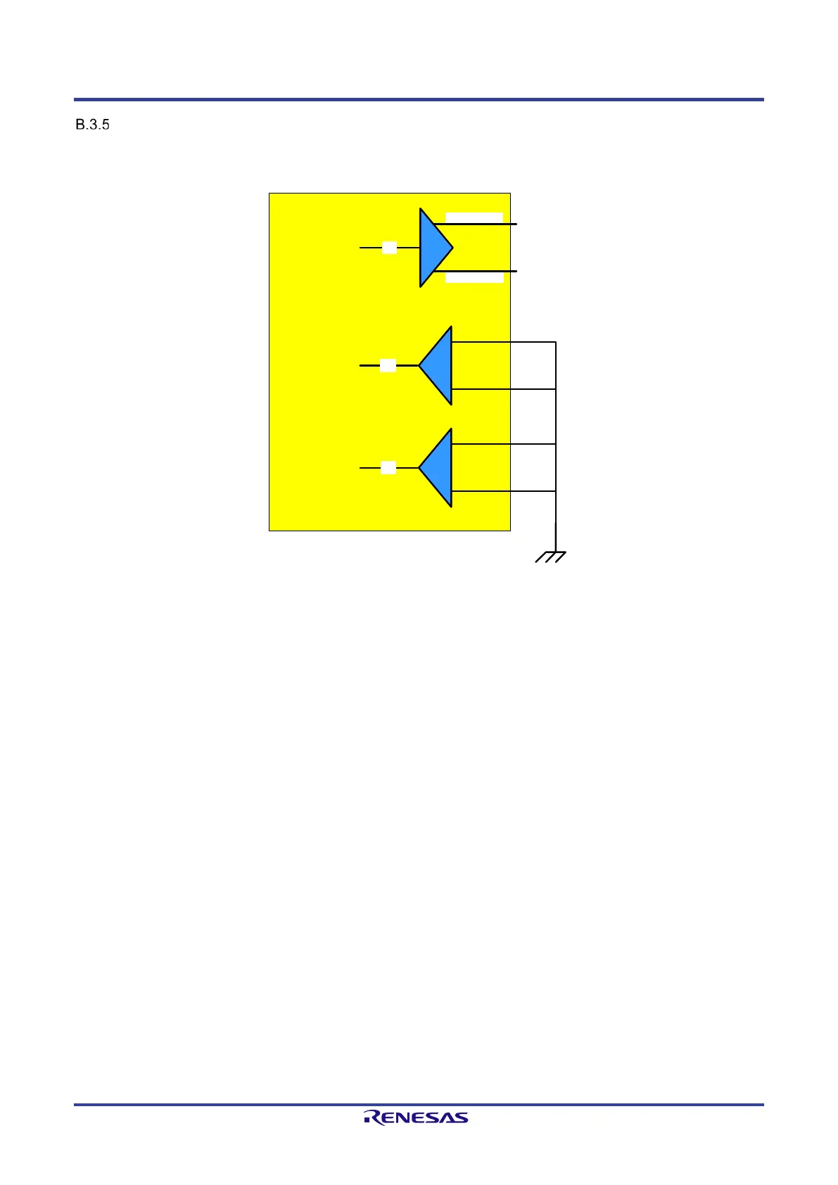
Unused 100Base-FX interface
Figure B-11 shows the wiring of an unused „Fiber Optic Transceiver“. The interface uses PECL lines.
If a 100Base-FX interface is not used, the pins Px_TD_OUT_P and Px_TD_OUT_N can remain open (no Pull-Up or Pull-Down resistor necessary).
All other signals should be connected to GND level.
open
open
TPS-1
Px_TD_OUT_P
Px_TD_OUT_N
TD
-
+
SD
+
-
Px_SD_P
Px_SD_N
RD
+
-
Px_RD_P
Px_RD_N
GND
3.3V PECL Input Buffer
3.3V PECL Output Buffer
3.3V PECL Input Buffer
Figure B-11: Unused pins at 100Base-FX interface
 Loading...