TPS-1 User’s Manual: Hardware 4. Shared memory structure
R19UH0081ED0107 Rev. 1.07 page 39 of 86
Jul 30, 2018
4.4. Interrupt Communication with the TPS-1
The communication between the TPS-1 and the Host CPU is processed by the Event-Unit. If you want to use the interrupt control, you need the
registers shown in Table 4-3.
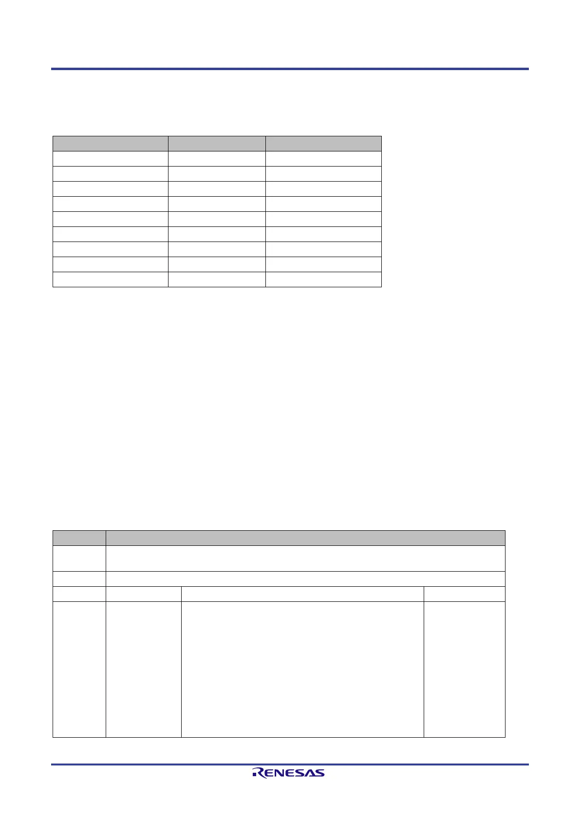
Table 4-3: Event Register List
Host_IRQ_low R/- 0x0008
Host_IRQmask_low R/W 0x0010
Host_IRQack_low -/W 0x0020
Host_EOI R/W 0x0028
PN_Event_high R/W 0x0040
4.4.1. How to generate an interrupt by an event
The following steps are necessary for generating an interrupt from an occurring event.
1. Set the mask register (low or high)
2. Acknowledge an Interrupt by deleting the event bits.
3. Write the Host_EOI register to reset the interrupt pin “INT_OUT”.
It is only necessary to set the mask register during the start sequence of your device once. Each occurring event has to acknowledge by writing the
Host_IRQack_low and Host_IRQack_high register.
After writing an acknowledge register the Host_EOI register must be written. The value written into this register disables the interrupt pin for the given
period (period: count * 10ns – Wait_Time). The interrupt signal is active high.
Note: You must write the register Host_EOI during the initialization (program start) to set the signal line to its passive
state (low level).
The register PN_Event_low and PN_Event_high is used to inform the external host about events. An ISR can check the event by reading these
registers.
Table 4-4: Register PN_Event_low
Name PN_Event_low
Access r/ w
31:00 Event-Bit
(HW-Events)
high active events
Bit 0:
Bit 1:
Bit 2:
Bit 3:
Bit 4:
Bit 5:
Bit 6:
Bit 7: Receive Output Data AR1
Bit 8: Receive Output Data AR0
Bit 9 – 15: reserved
Bit 16 – 31: further use
0X00000000
 Loading...