TPS-1 User’s Manual: Hardware 9. Clock Circuit
R19UH0081ED0107 Rev. 1.07 page 56 of 86
Jul 30, 2018
9. Clock Circuit
9.1. Using the internal clock oscillator
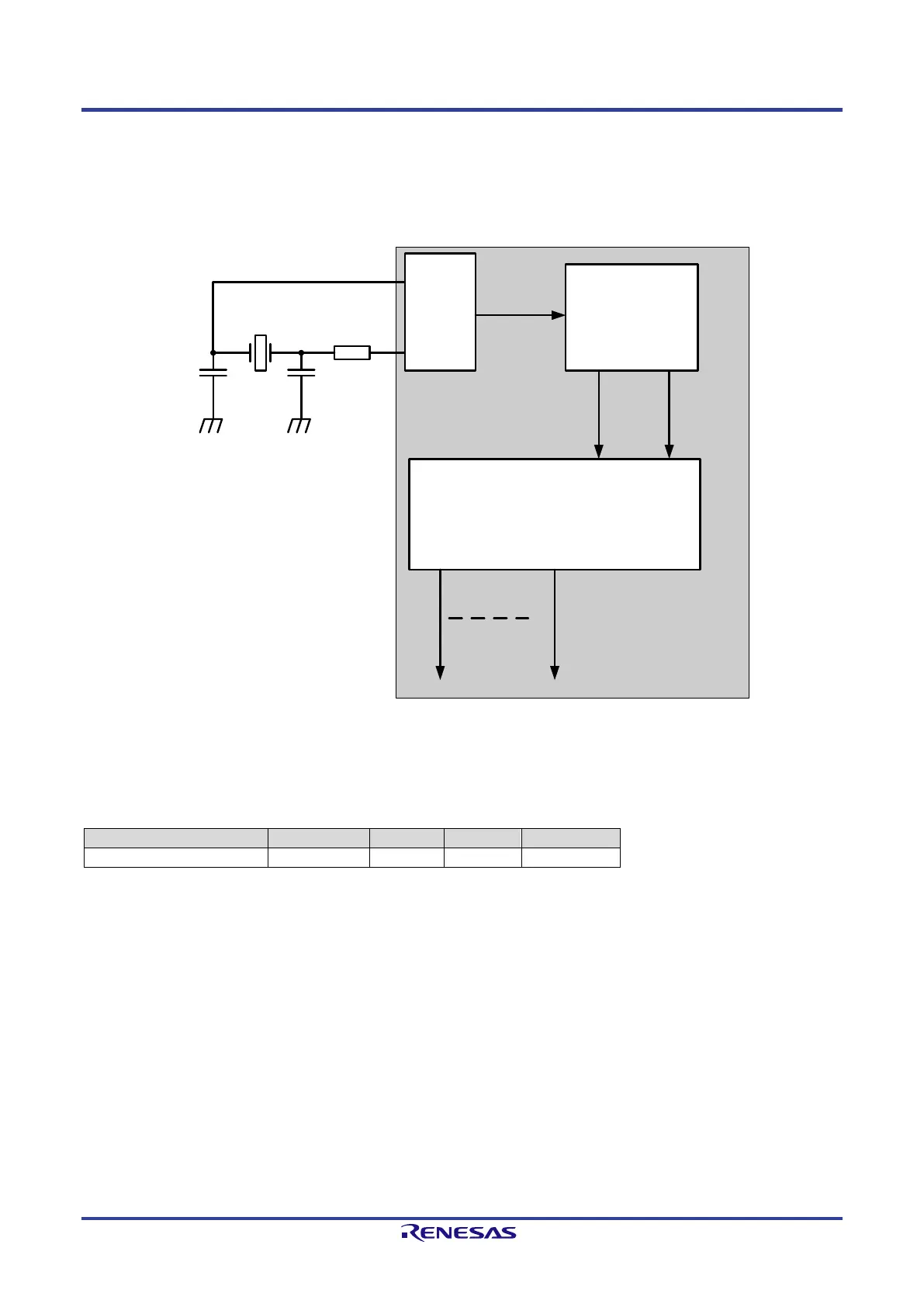
The clock distribution of the TPS-1 requires an oscillator with 25 MHz (XCLK1, XCLK2). All necessary internal clock signals are derived from this
external clock (internal clock unit).
25 MHz
Oscillator
APPL
(REFCLK * 16)
REFCLK
(25 MHz)
CLK_UNIT
PLL_LOCK
CLK400M
CLK_ARM
(100 MHz)
CTS0
XCLK1
XCLK2
Rv
Cin Cout
Figure 9-1: Wiring of the TPS-1 clock
The recommended circuitry (Figure 9-1: Wiring of the TPS-1 clock) is based on the Seiko Epson TSX-3225 Crystal Unit. It is recommended to use this
crystal and circuitry recommendation (using Seiko Epson crystal). In any case it is the customer’s responsibility to verify, whether crystal, circuitry and
layout fulfill the requirements.
Table 9-1: Example for an oscillator crystal
Note that the oscillator frequency must be 25 MHz, otherwise the PLL will not operate properly.
If a different crystal is used the following conditions have to be met:
• Crystal with 25 MHz with a maximum of +/- 50 ppm over the whole lifetime and
temperature range.
• The values for R
V
, C
IN
and C
OUT
have to be calculated accordingly (please contact the crystal provider)
 Loading...