TPS-1 User’s Manual: Hardware 8. PROFINET IO switch
R19UH0081ED0107 Rev. 1.07 page 53 of 86
Jul 30, 2018
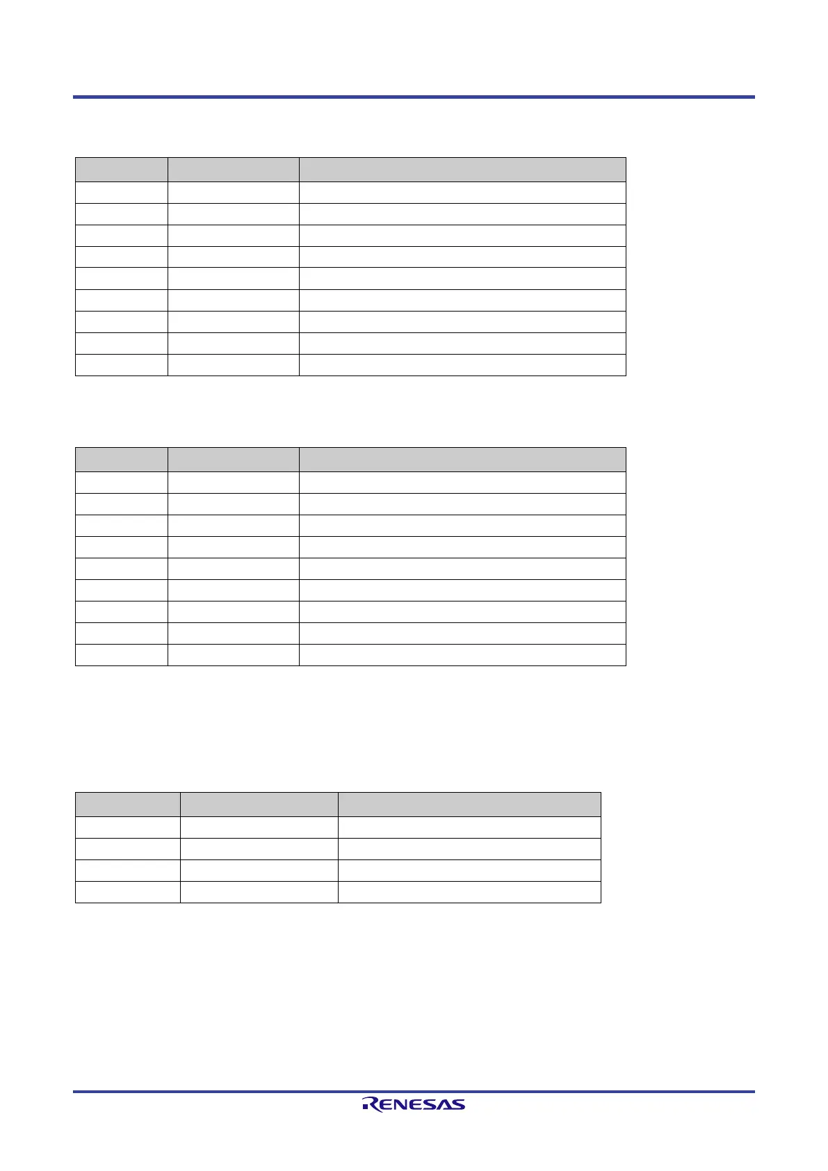
8.2.1. 100Base-FX interface (Port 1)
Table 8-4: Signal lines 100Base-FX interface (Port 1)
Pin Designation Description
C9 I2C_1_D_INOUT I
2
C data line
B8 P1_SD_P Signal detect (Difference +)
Signal detect (Difference -)
A9 P1_RD_N Receive signal (Difference -)
Receive signal (Difference +)
A5 P1_FX_EN_OUT Transmitter enable (transceiver output)
Transmit signal (Difference +)
A6 P1_TD_OUT_N Transmit signal (Difference -)
8.2.2. 100Base-FX interface (Port 2)
Table 8-5: Signal lines 100Base-FX interface (Port 2)
Pin Designation Description
M11 I2C_2_D_INOUT I
2
C data line
N8 P2_SD_P Signal detect (Difference +)
Signal detect (Difference -)
P9 P2_RD_N Receive signal (Difference -)
Receive signal (Difference +)
P5 P2_FX_EN_OUT Transmitter enable (transceiver output)
Transmit signal (Difference +)
P6 P2_TD_OUT_N Transmit signal (Difference -)
8.3. I2C-Bus – LWC Diagnostic
The TPS-1 provides two “I
2
C Interface Lines” for fiber optics diagnostic purposes. The recommended AVAGO transceiver (AFBR-5978Z) features
internal registers that can be read by the I
2
C interface. The transceiver can deliver diagnostic information via the I
2
C interface. If signal quality is
dropping, an alarm indication can be sent to the controller.
Table 8-6: I
2
C interface lines
Pin Signal TPS-1 Description
2
C6 SCLK_1_INOUT Fiber Optic Port1 I
2
C-Bus “Clock”
2
L11 SCLK_2_INOUT Fiber Optic Port2 I
2
C-Bus “Clock”
 Loading...