TPS-1 User’s Manual: Hardware 3. Host Interface
R19UH0081ED0107 Rev. 1.07 page 28 of 86
Jul 30, 2018
3.3.2. SPI Slave Interface Timing
The SPI transfer is controlled by the signal HOST_SFRN_IN. A chip select signal is not used.
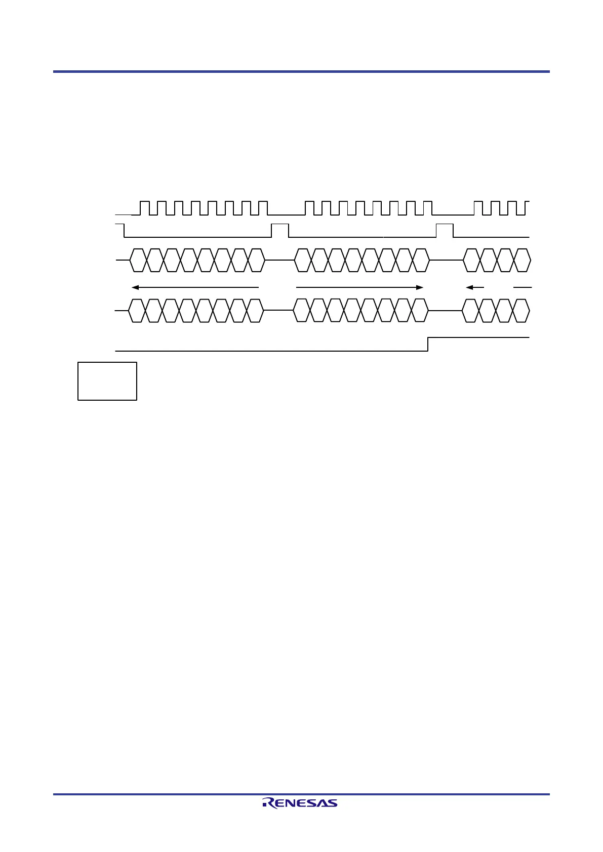
3.3.2.1. SPI Slave Interface Typical Timing
The following figure shows a typical SPI-Slave Timing (Motorola Mode).
Each transfer (a transmission of 8 bit) starts with a falling edge of the HOST_SFRN_IN signal. The transmission is controlled by the clock signal. All
receive and transmit data is processed in the Little-Endian format by the serial host interface. When connecting a Big-Endian Host System, the format
has to be changed into the correct order.
There is a maximum clock frequency of 25 MHz possible using this interface.
B7 B6 B5
B4 B3 B1B2 B0 B15 B14 B13 B12 B11 B9B10 B8 B7 B6 B5 B4
HOST_SCLK_IN
SPI-Header
SPI-Data
B7 B6 B5 B4 B3 B1B2 B0
B15 B14 B13 B12 B11 B9B10 B8
Dumm
y
Dumm
y
Dumm
y
Dumm
y
MSBit
LSBit LSBit
MSBit
HOST_SFRN_IN
HOST_SRXD_IN
HOST_STXD_IN
HOST_SHDR_OUT
Motorola SPI
format:
SPO = 0
SPH = 0
Figure 3-10: SPI Slave Timing
The signal HOST_SHDR_OUT is used to inform the SPI master, that header information has been received (HOST_SHDR_OUT = 0). When the
signal goes to high level (HOST_SHDR_OUT = 1), payload data is expected.
 Loading...