TPS-1 User’s Manual: Hardware 3. Host Interface
R19UH0081ED0107 Rev. 1.07 page 29 of 86
Jul 30, 2018
As soon as the signal HOST_SFRN_IN is set to “1”, no more data is received on the RxD interface. Setting the signal is not allowed during an ongoing
transfer.
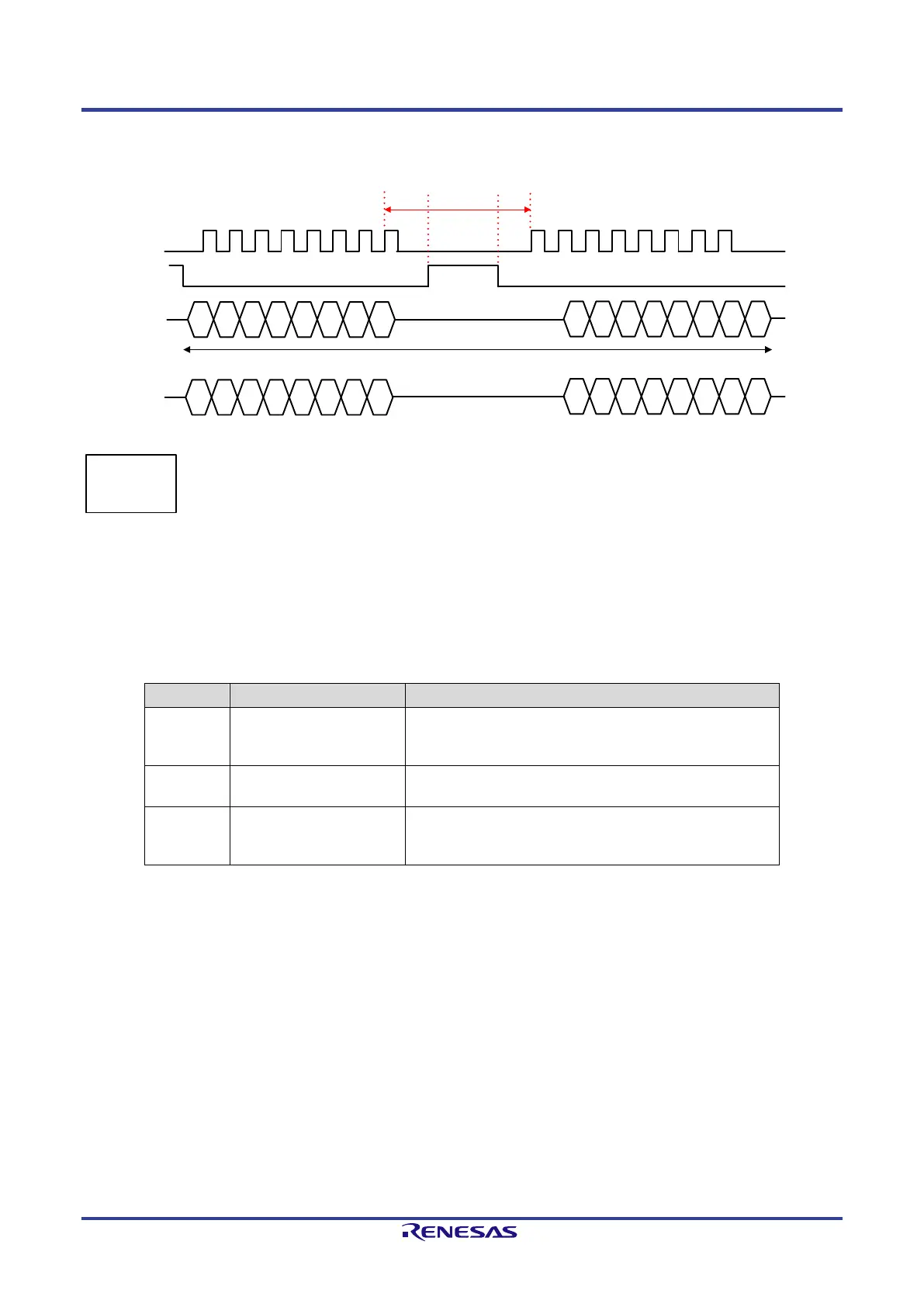
B7 B6 B5 B4 B3 B1B2 B0
B15 B14 B13 B12 B11 B9B10 B8
HOST_SCLK_IN
B7 B6 B5
B
4 B3 B1B2 B0
B15 B14 B13 B12 B11 B9B10 B8
MSBit
LSBit
LSBit
MSBit
HOST_SFRN_IN
HOST_SRXD_IN
HOST_STXD_IN
Motorola SPI
format:
SPO = 0
SPH = 0
T1
T2 T3
2 Byte
Figure 3-11: SPI Transfer with HOST_SFRN_IN Signal
The HOST_SFRN_IN signal is required to synchronize bytes transferred to the TPS-1 with the peripheral interface. The timing to be observed can be
seen in Figure 3-11 (T1, T2 and T3).
The timing is based on the system clock of the TPS-1 (100 MHz, 10 ns); it must as well be applied in the situations shown in Figure 3-12, Figure 3-13
and Figure 3-14.
Table 9: Timing HOST_SFRN_IN signal
Phase Timing Description
The HOST_SFRN_IN signal may become active not
earlier than one system clock after the rising edge of
HOST_SCLK_IN.
T2 min. 2 system clock The signal HOST_SFRN_IN must be active for at least
2 system clocks.
There must be at least 3 system clocks between the
falling edge of HOST_SFRN_IN and the active edge of
HOST_SCLK_IN.
 Loading...