TPS-1 User’s Manual: Hardware 5. TPS-1 boot subsystem
R19UH0081ED0107 Rev. 1.07 page 43 of 86
Jul 30, 2018
5. TPS-1 boot subsystem
During each startup of the TPS-1, the firmware and the configuration are read from the boot Flash. The configuration contains also the MAC addresses
for the network ports which connect the device to other PROFINET IO devices.
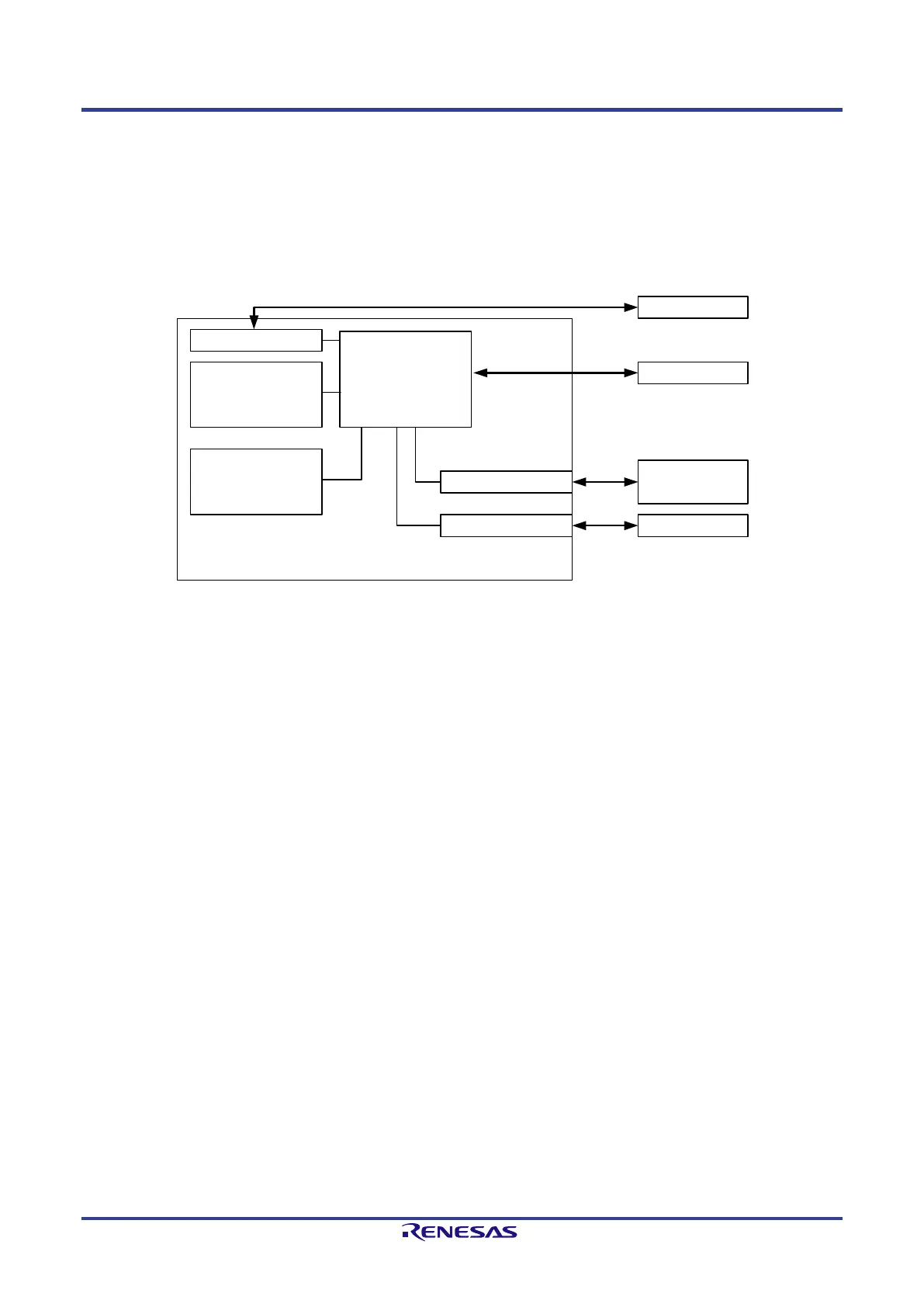
5.1. Hardware Structure for the Boot Operation
The TPS-1 uses a boot loader which reads all necessary data from the boot Flash and carries out the necessary settings. The boot loader is integrated
into the ASIC and cannot be changed.
Boot Flash
(SPI-Slave)
JTAG-Interface
PROFINET
CPU-Core
Internal RAM
Boot ROM
SPI-Master Interface
Ethernet Interface LAN-Interface
JTAG-Connector
TPS-1
UART-Interface
Figure 5-1: TPS-1 structure for the boot process
During the manufacturing process, the following data have to be written to the boot Flash:
• manufacturer information
• device data, device configuration
• I&M information
• operating mode of the TPS-1
• MAC addresses
• PROFINET CPU firmware (Target Host Image)
The necessary data for the boot Flash is assembled by the configuration tool TPS Configurator.
 Loading...