TPS-1 User’s Manual: Hardware 4. Shared memory structure
R19UH0081ED0107 Rev. 1.07 page 42 of 86
Jul 30, 2018
You can verify the interrupt event sources by reading the Host_IRQ_low and Host_IRQ_high register. Each bit corresponds with a masked event. A bit
set to “1” shows a masked bit.
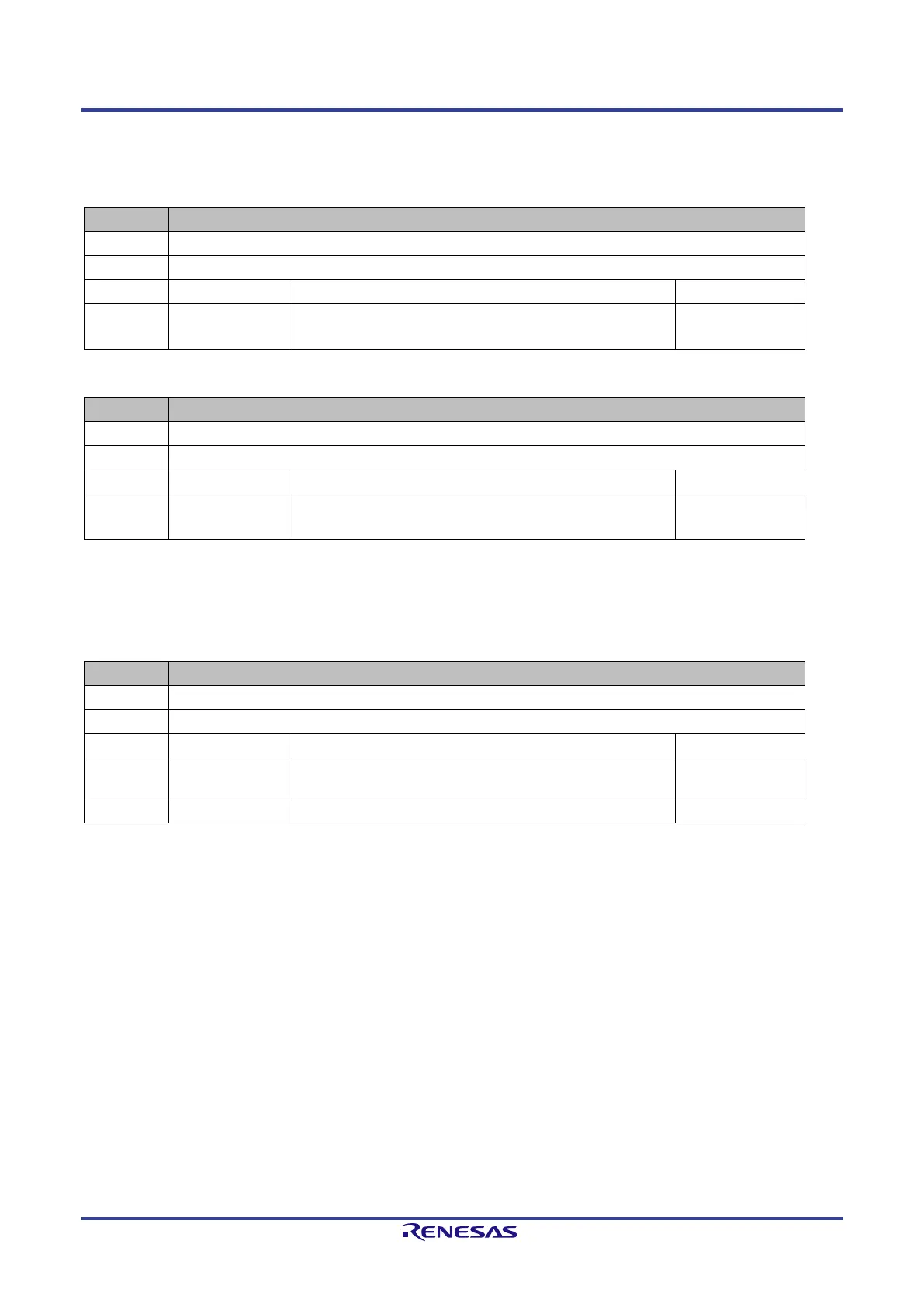
Table 4-10: Register Host_IRQ_low
Address 0x0008
Bits Type of Event Description Init:
“0”: PN_Event_low = “0” or Host_IRQMask_low = “1”
“1”: PN_Event_low = “1” and Host_IRQMask_low = “0”
Table 4-11: Register Host_IRQ_high
Address 0x000C
Bits Type of Event Description Init:
“0”: PN_Event_low = “0” or Host_IRQMask_low = “1”
“1”: PN_Event_low = “1” and Host_IRQMask_low = “0”
The deactivation of the interrupt pin (INT_OUT) is processed by writing into the register “Host_EOI” (0x0028). A new activation of the interrupt pin
depends on the written value (bits 17:00 – Wait_Time). The activated events can be identified by reading the register Host_IRQ_low and
Host_IRQ_high.
Table 4-12: Register Host_EOI
Access r/ w
17:00 Wait_Time Period of deactivating of the interrupt pin (INT_OUT).
(Number of entities * 10ns – max. value 2,6 ms)
0X00000
 Loading...